New colorimeter open hardware design expands flexibility
Our open hardware colorimeter is a popular tool for measurements analytes using colorimetric assays. We initially designed the colorimeter as an educational kit in 2012 with Kickstarter funding.
Our open hardware colorimeter is a popular tool for measurements analytes using colorimetric assays. We initially designed the colorimeter as an educational kit in 2012 with Kickstarter funding. However, since our original design there have been significant developments in open source hardware and we felt a redesign could allow us to take advantage of some of the developments to make the colorimeter more flexible and easier to use.
Communication with peripheral devices via I2C using 4-wire cables with JST SH connectors, such as Sparkfun Qwiic or Adafruit STEMMA QT, is rapidly becoming a standard on new development boards. This standardized cabling allows multiple sensors to be connected to the development board without any soldering. By using these standardized connectors our colorimeter compatibile with the large and growing variety of development boards that support this standard.
Our original colorimeter was designed to connect to the Arduino Uno using a shield. This limited it use to the Arduino Uno. The new design, because of its standardized cabling, works with any development board supporting this standard, for example Adafruit Feather RP2o40, FeatherS2, Sparkfun Qwiic ProMicro, Sparkfun RedBoard Qwiic and many others. It will also work with the larger 4-pin STEMMA connectors with a JST PH to JST SH adapter cable so that development boards such as the PyBadge and PyGamer can be used - both of which are ideal for making standalone instruments. Finally, for those wishing to use the Raspberry Pi a Qwiic HAT adapter is available from Sparkfun.
Colorimeter components
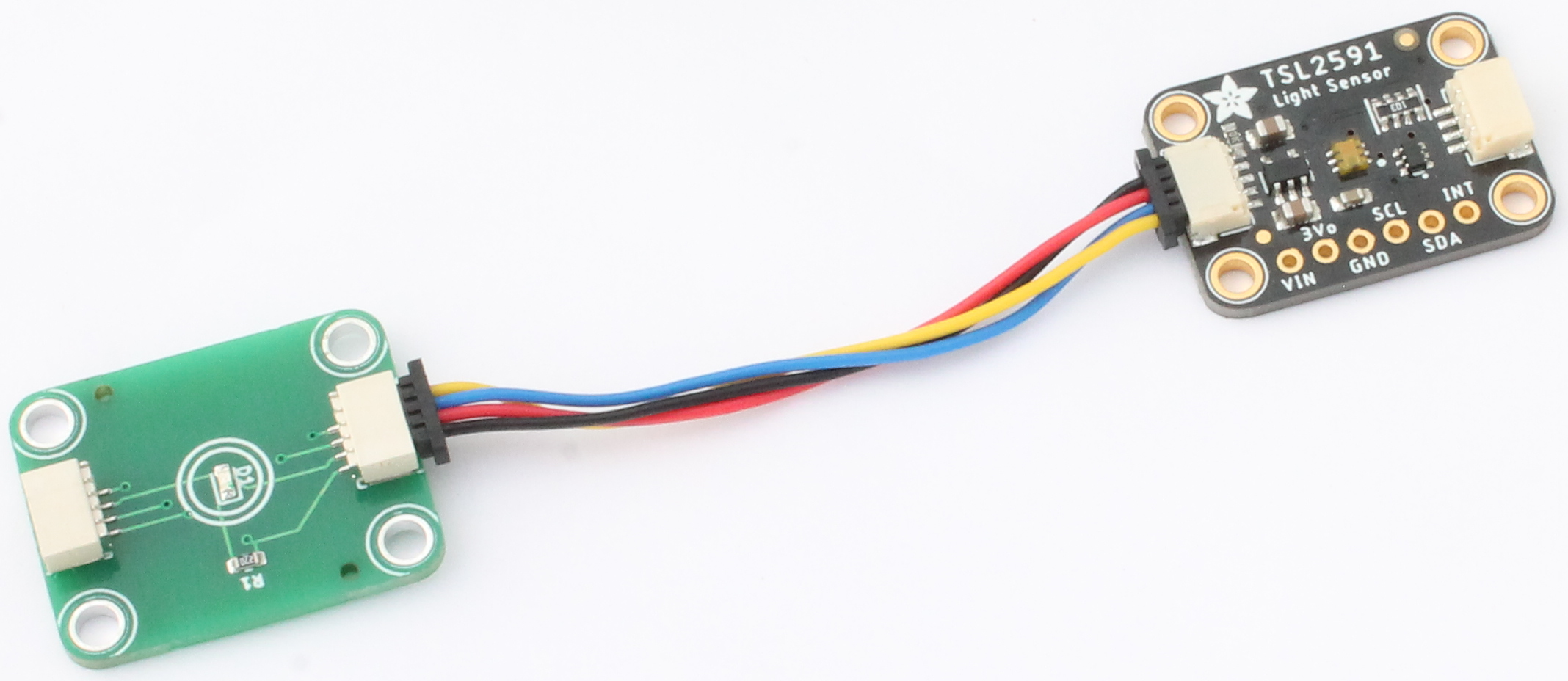
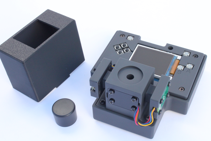
There are 3 main components to the new colorimeter hardware design - 1) Adafruit tsl2591 light sensor board 2) LED boards with custom wavelengths and 3) cuvette holder. In addition there are two JST SH cables and a light-blocking cover.
1. Light Sensor Board
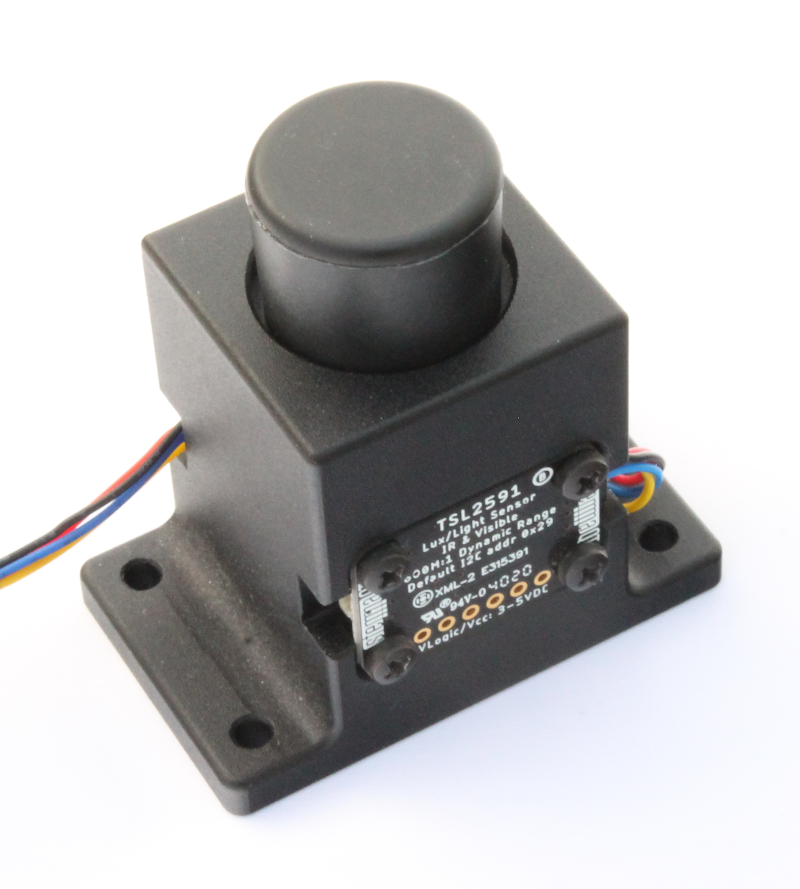
The Adafruit TSL2591 High Dynamic Range Digital Light Sensor is a broad range light sensor in a small form factor which works well with our new the cuvette holder. It comes with the standard 4-pin JST SH connectors (also called STEMMA QT or Qwiic) described above . The open hardware design files and lots of other documentation can more can be found here: https://learn.adafruit.com/adafruit-tsl2591.
2. LED Board
We designed a complimentary LED board with approximately the same form factor as the Adafruit light sensor board. The LED board is connected to the light sensor board via a 4-pin cable and JST SH connectors. The open hardware KiCad design files can be found here: https://github.com/iorodeo/i2c_led
Features
- Dimensions: 25.4 mm x 20 mm x 1.6 mm
- Two 4-pin JST SH connectors
- Four M2.5 through holes for mounting to the cuvette holder
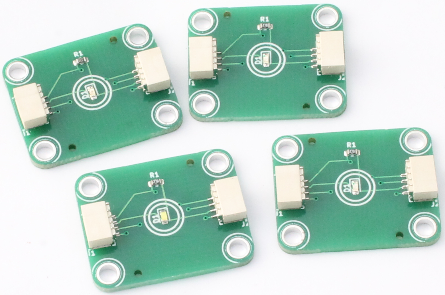
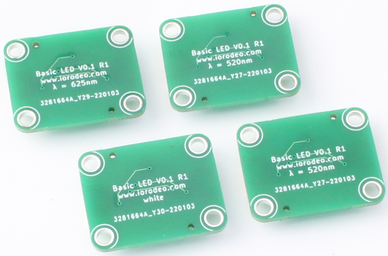
- Surface mount LED and resistor. Any 0603 LED can be used here. For example, we have made boards with white, blue (470nm), green (520nm) and red (625nm) LEDs as shown in the images below
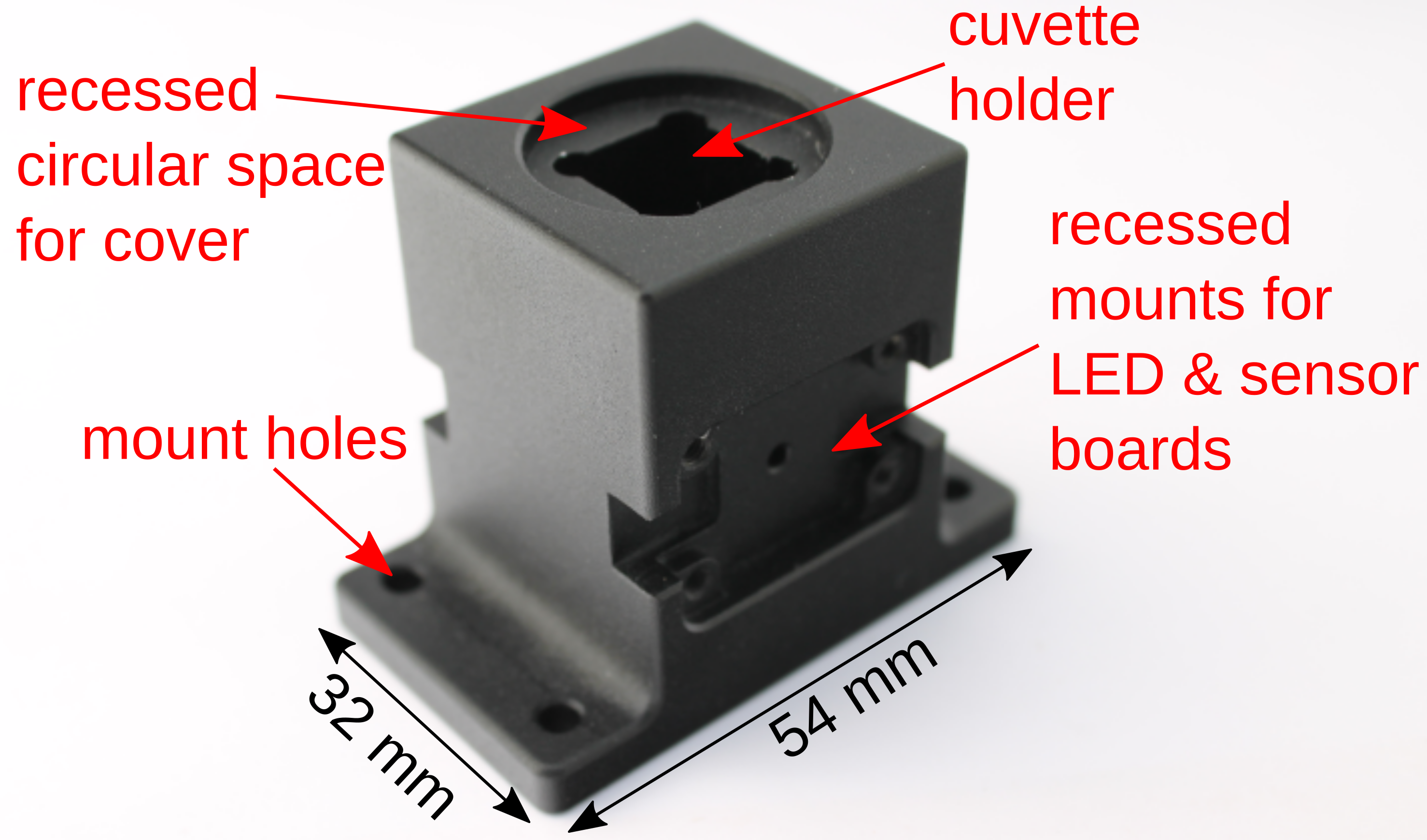
2. Cuvette holder
The cuvette holder was designed using FreeCAD. The open source hardware design files are here: https://github.com/iorodeo/cuvette_holder.
Features
- Material: 6061 aluminum in anodized black (shown here) or 3D printed black nylon plastic (not shown)
- Dimensions: 54 mm (length) x 32 mm (width) x 43.5 mm (height)
- Fits 12 cm x 12 cm cuvettes (pathlength = 10 cm)
- Recessed circular space for a light-blocking cover
- Recessed mounts on either side with tapped M2.5 threads (for mounting the LED and light sensor boards)
- Base flange with 4 mount holes for (optionally) mounting the cuvette holder onto another part
Assembly of the colorimeter
Assembly is very simple with no soldering required! The first step is to connect the LED and light sensor boards with a 4-pin JST PH cable
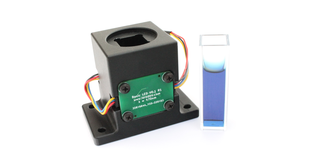
The next step is to mount these on opposite sides of the cuvette holder using M2.5 machine screws as shown in the image below. In these images below we also have a second cable daisy-chained to the LED board for connecting to a development board or the host PC.
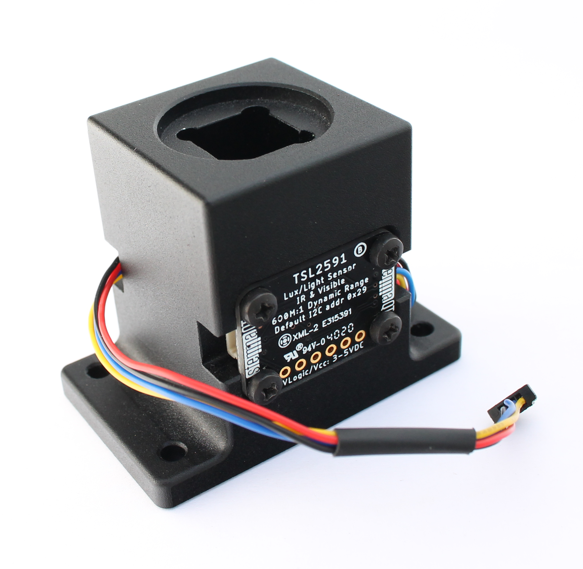
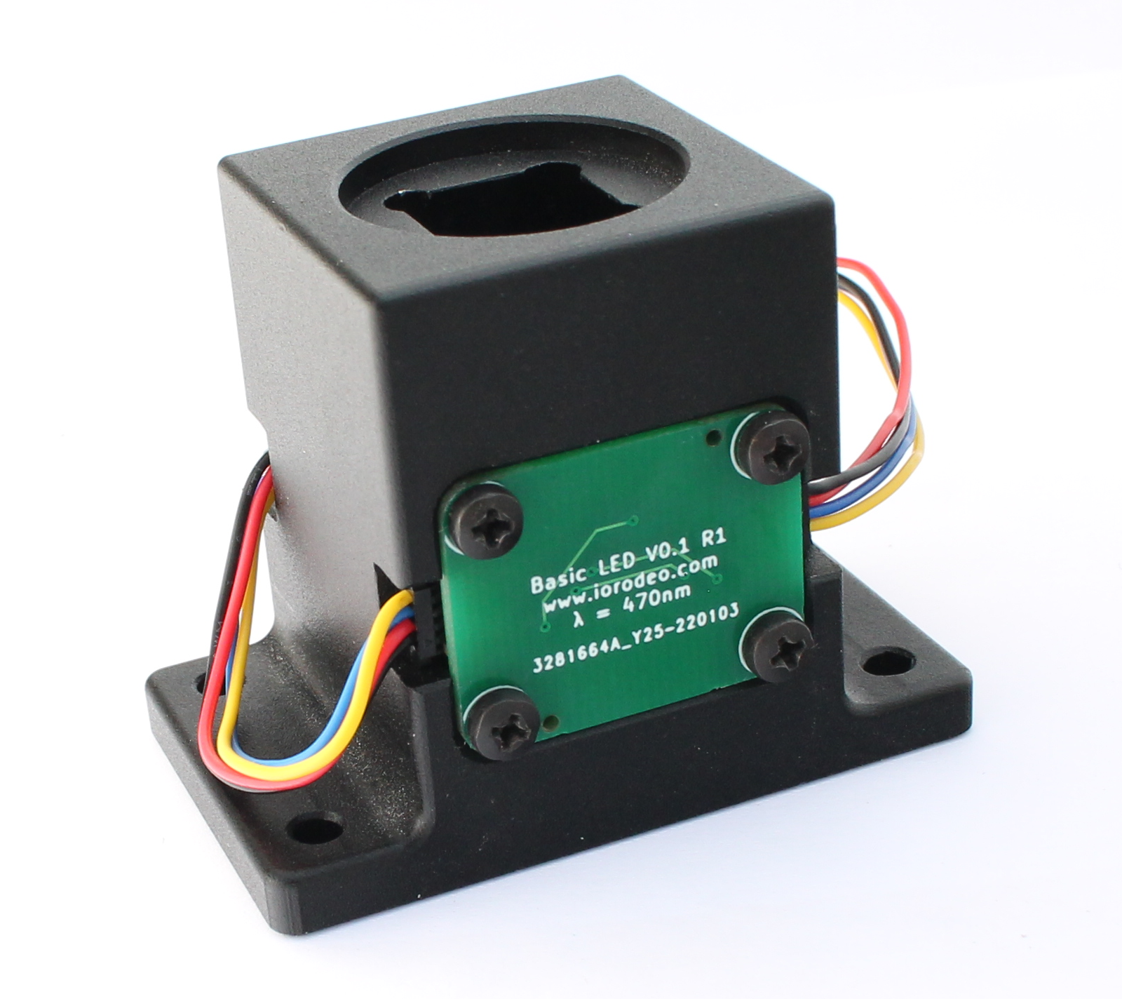
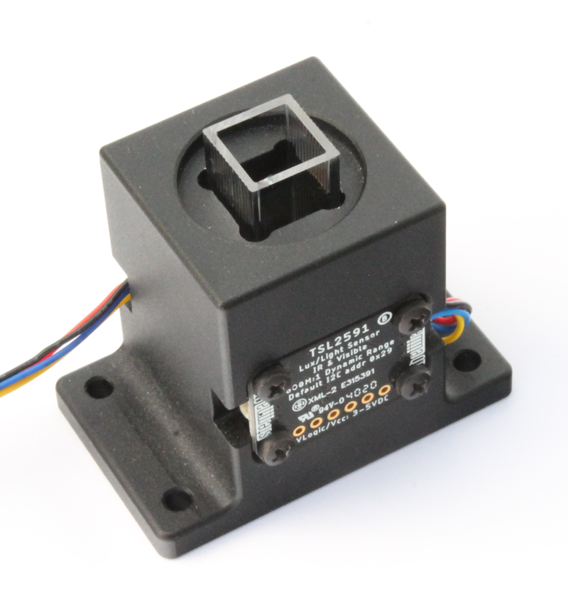
The images below show the assembled colorimeter with a cuvette and light-blocking cover.
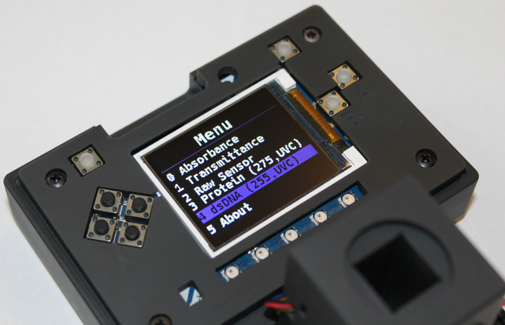
Next Steps - Colorimeter software
We are currently working on example firmware (in circuitpython) and software (Python) demonstrating how to take absorbance measurements using the colorimeter. Blog post documenting the open source software and product link to buy the colorimeter are coming soon!
Comments ()