Setting up an Outdoor Air Quality Sensor with the Feather Tripler
This tutorial covers how to build an open hardware air quality sensor for indoor or outdoor monitoring using the Feather Tripler PCB.
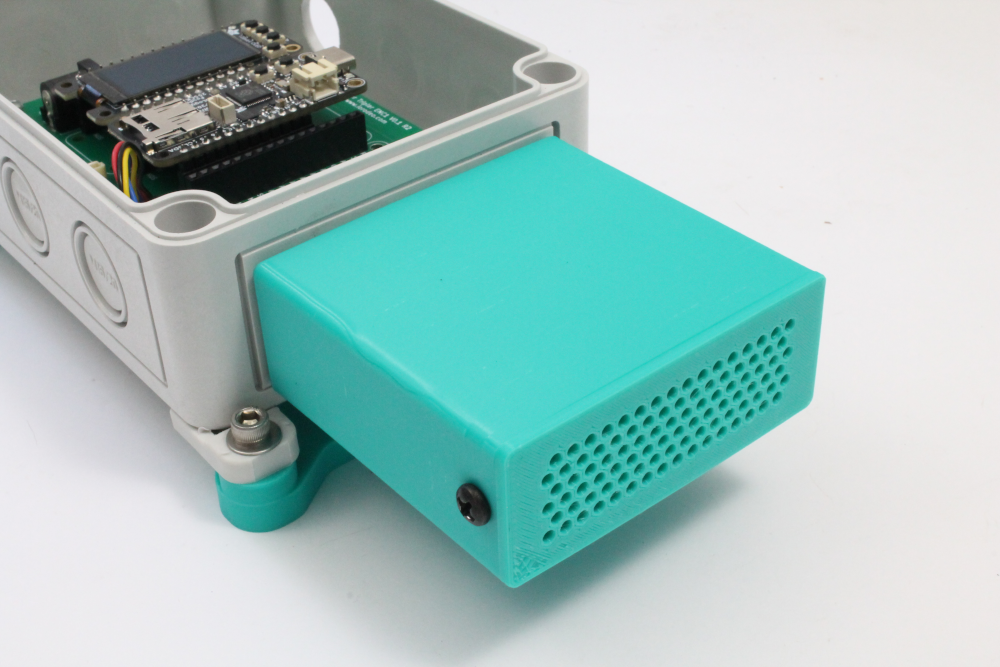
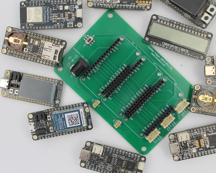
In a previous post we introduced the Feather Tripler PCB. This carrier board can be used with the Adafruit Feather ecosystem, a waterproof enclosure and sensors of choice to rapidly prototype outdoor monitoring projects.
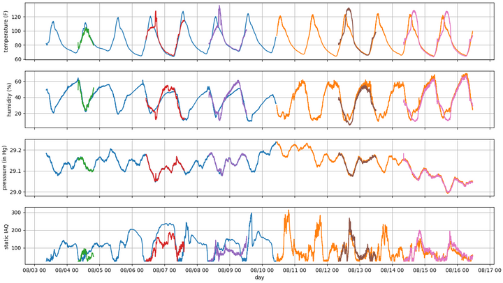
In this post we show an example of how to assemble an outdoor monitor to collect temperature, humidity, pressure, air quality (AQI) and particulate matter (PM 1, 2.5 & 10) data using the Feather Tripler. In this example we are using the same BME688 sensor we used previously in our outdoor monitoring project along with an added PM sensor. These sensors are just shown as an example, but other air quality sensors can be used.
Hardware BOM
The total parts cost is $250.
- Feather Tripler PCB, $28
- Feather RP2040 Adalogger, $14.95
- FeatherWing OLED 128x64, $14.95
- PMSA003I Air Quality Breakout, $44.95
- BME688 Temperature, Humidity, Pressure and Gas Sensor, $19.95
- SK-15 enclosure with clear top, $20.92
- SK-97 Spacer Kit for SK Series Enclosures, $1.35
- Waterproof cable gland, $3.16
- STEMMA QT/Qwiic cable, 50 mm long, $1.05
- STEMMA QT/Qwiic cable, 100 mm long, $0.95
- Voltaic 5V solar system, $99. Alternatively you could use a 5V wall adapter for indoor monitoring
- 3D-printed sensor housing and hardware (optional)
Assembly Steps
Once you have all the parts in the BOM gathered, assembly is fairly straightforward. The only additional tools used are screwdrivers. No machining or soldering is required.
Step 1: Prepare the enclosure
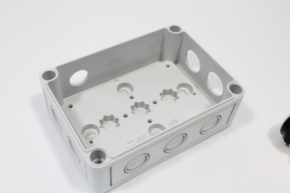
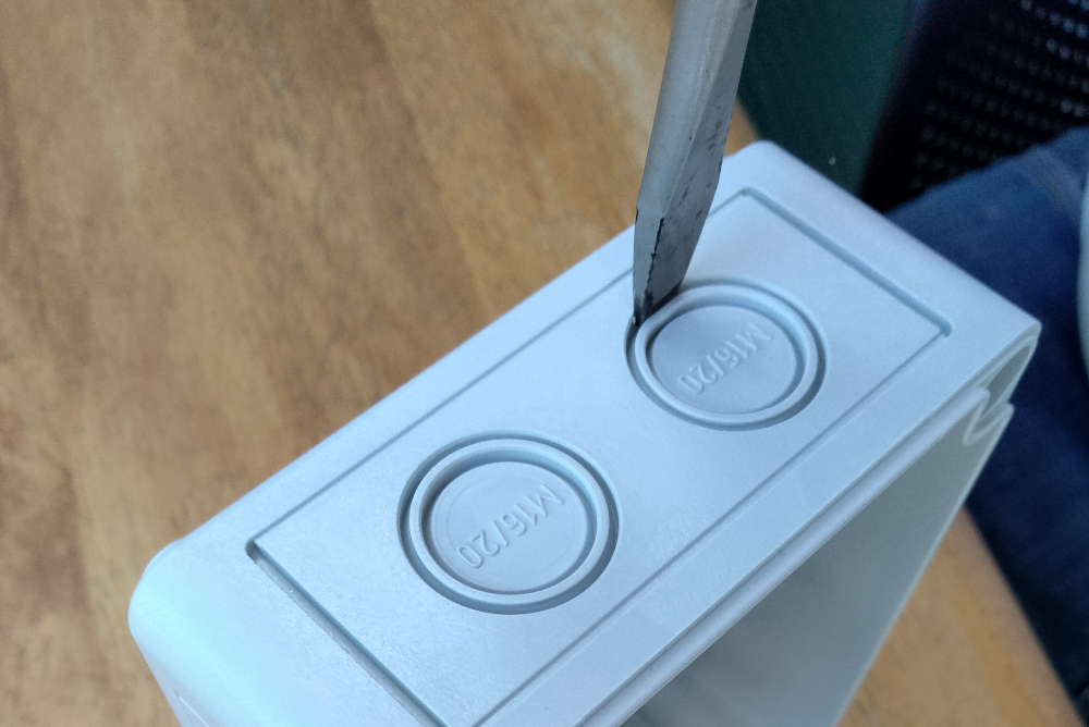
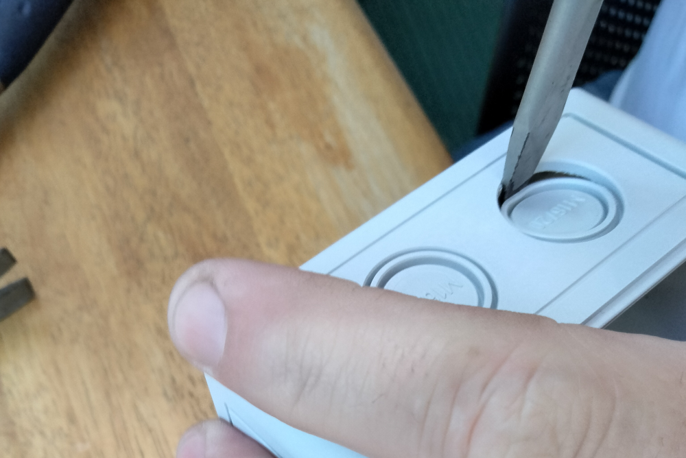
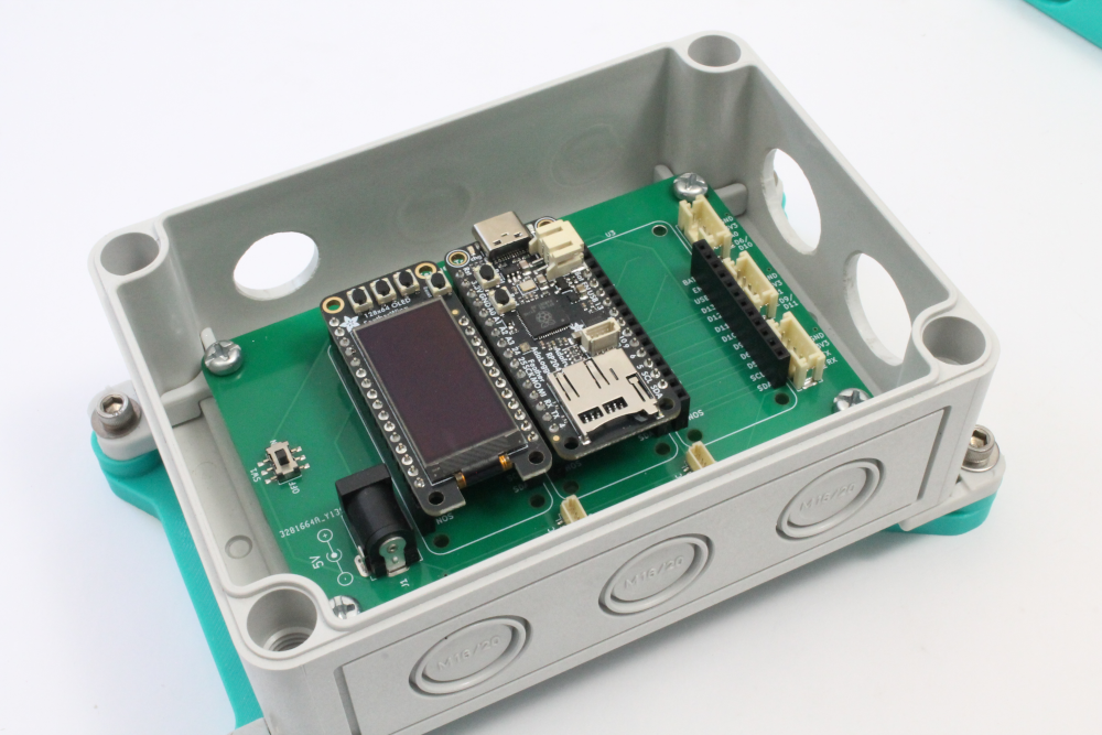
Follow the instructions linked below to remove 3 of the M16/20 knockouts using a flat-end screwdriver. The hole pattern should match the image below.
Step 2: Mount the Feather Tripler, Feather and FeatherWing
Mount the Feather Tripler into the enclosure using the SK-15 PCB mounting kit. Note the orientation shown below with the 5V power connector facing the single knockout. Mount the Feather RP2040 Adalogger and FeatherWing OLED as shown here.
Step 3: Mount the two air quality sensors
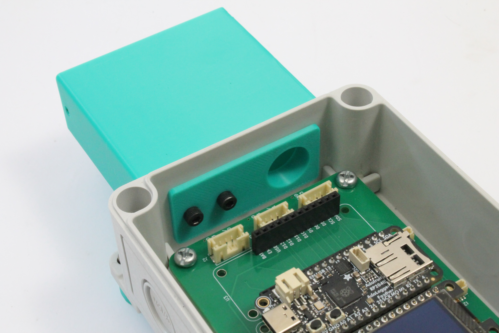
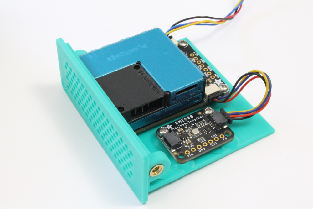
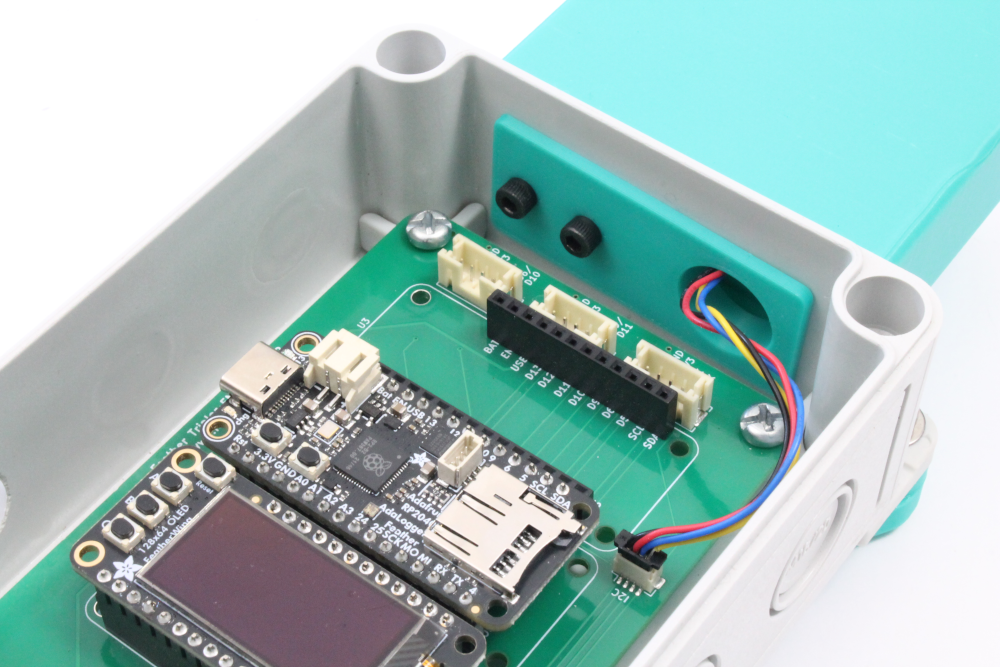
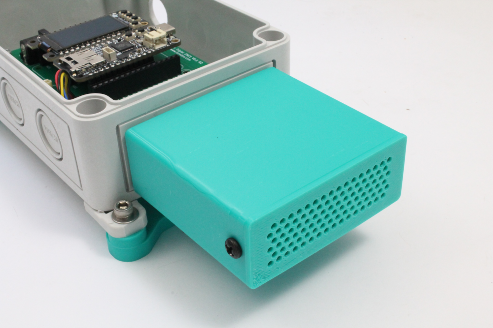
For this part you will need to print and prepare the 3D-printed parts as described on this page. Once you have these parts and the necessary hardware ready, attach the "sensor box" to the enclosure using the other two knockouts and mount the sensors on the "sensor tray". Connect the two sensors with the 50mm cable. Connect one end of the 100mm cable to the air quality breakout board.
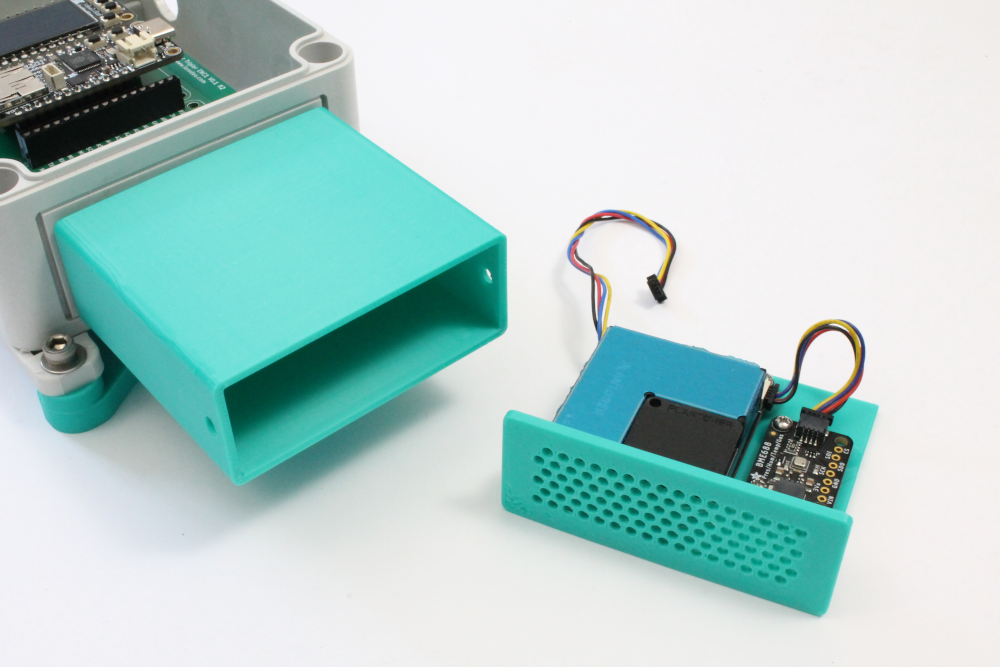
Slide the tray into the housing with the end of the 100 mm long cable passing through the knockout in the SK-15. Connect this to the I2C header on the Feather Tripler. Secure the sensor housing in place with two screws.
Step 4: Power entry and lid
Prepare the solar panel entry as described in Step 5 of the Open Water Level Sensor Kit. With the power switch in the OFF position, connect the end of the solar power cable into the barrel connector on the PCB and tighten down the waterproof cable gland.
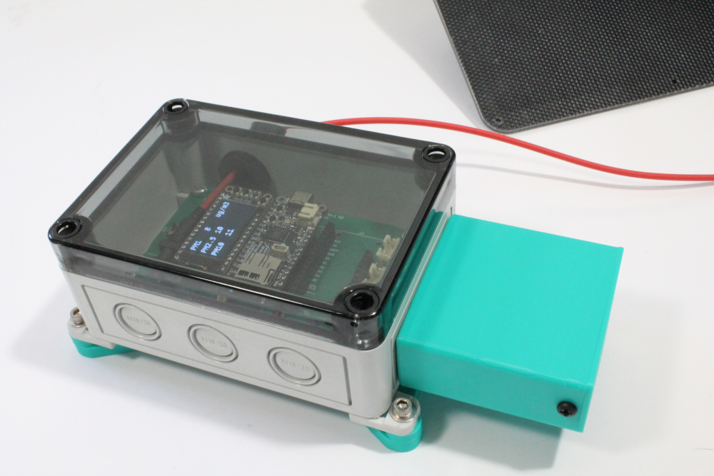
Slide the power switch to the ON position and check the display is now returning the sensor data. Finally, place the clear lid over the enclosure and tighten in place with a flat-head screwdriver.

Next Steps
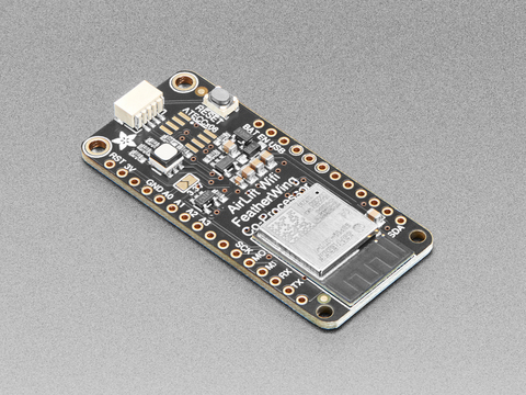
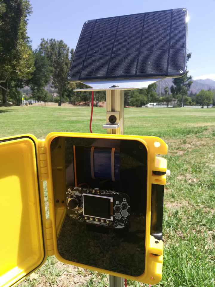
For the next steps we will be finishing up the RP2040 Adalogger Sample Code (currently in draft) and mounting the air quality sensor outdoors to start collecting data. We will also explore streaming data using the Adafruit AirLift FeatherWing in a future post.


Comments ()