Miraculix Photometer Kit: Assembly Instructions
The Miraculix photometer kit is designed for customers to easily build their own photometer for use with the QTest kits. The photometer kit contains all of the parts needed and will be available to purchase from our EU stores soon!
For more information on using the photometer with the quantitative QTests visit: LINK HERE
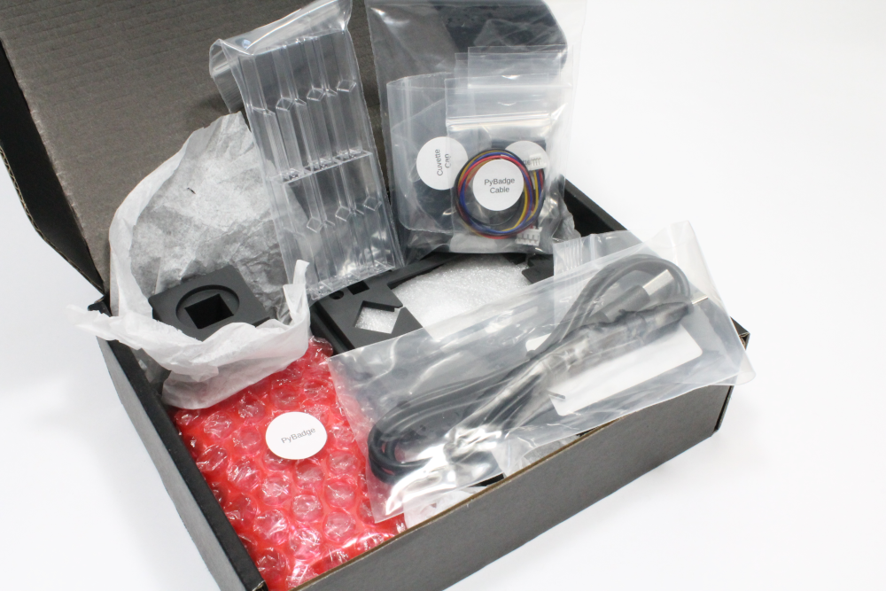
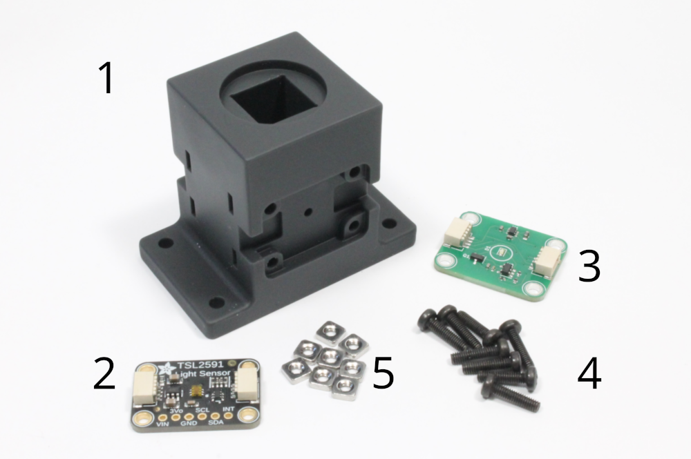
Kit Contents: each kit contains the following parts
- Cuvette Holder
- Adafruit TSL2591 Light Sensor Board (with indicator LED disabled)
- IO Rodeo 595nm LED board
- 8 x 10 mm long M2.5 Phillips head screws
- 8 x M2.5 thin-profile square nuts
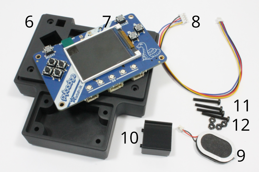
- PyBadge Enclosure
- Adafruit PyBadge
- 200 mm PyBadge Cable
- Mini Speaker
- Battery Holder
- 4 x 20 mm long M2.5 Phillips head screws
- 4 x M2.5 hex nuts
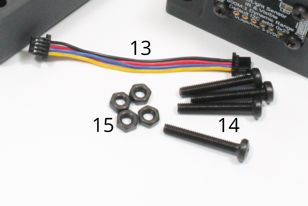
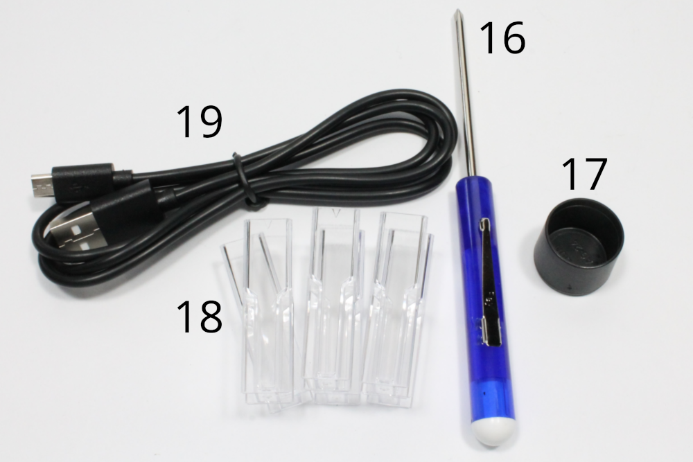
- 50 mm flexible cable
- 4 x 20 mm long M3 Phillips head screws
- 4 x M3 hex nuts
- Mini screwdriver
- Cuvette Cap
- 6 x 1.5 mL disposable cuvettes
- USB cable A/micro B
Step 1: Light sensor and LED assembly
- The cuvette holder has two different sides for mounting the light sensor and LED side. You can start assembly on either side.
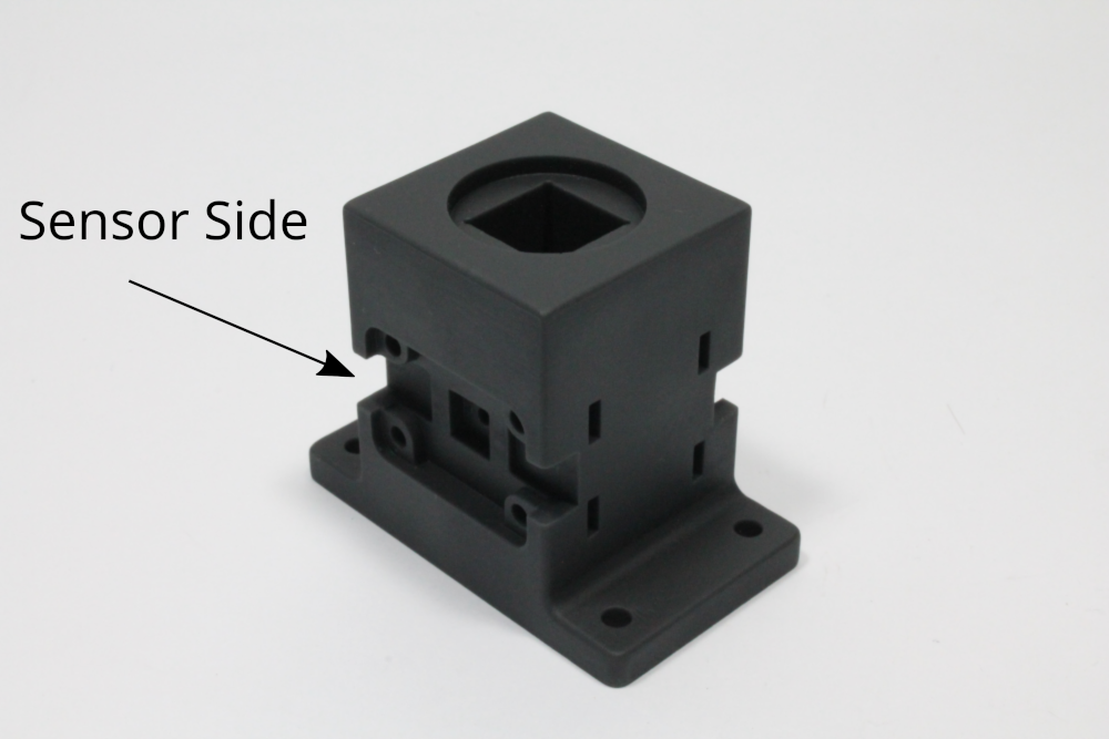
- Lie the cuvette holder flat with the sensor-side up
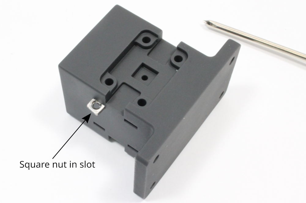
- Place 4 of the square nuts into the slots on the side of the cuvette holder
- Place the sensor board face down in the cutout
- Place a screw into one of the corner holes in the sensor board and use the screwdriver to tighten the screw
- Repeat until all 3 corner screws are in place
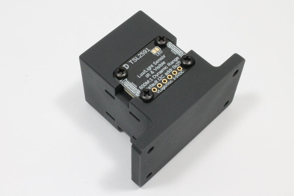
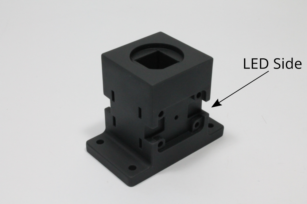
- Repeat these steps for the LED side using the LED boards and remaining 4 sets of nuts and screws
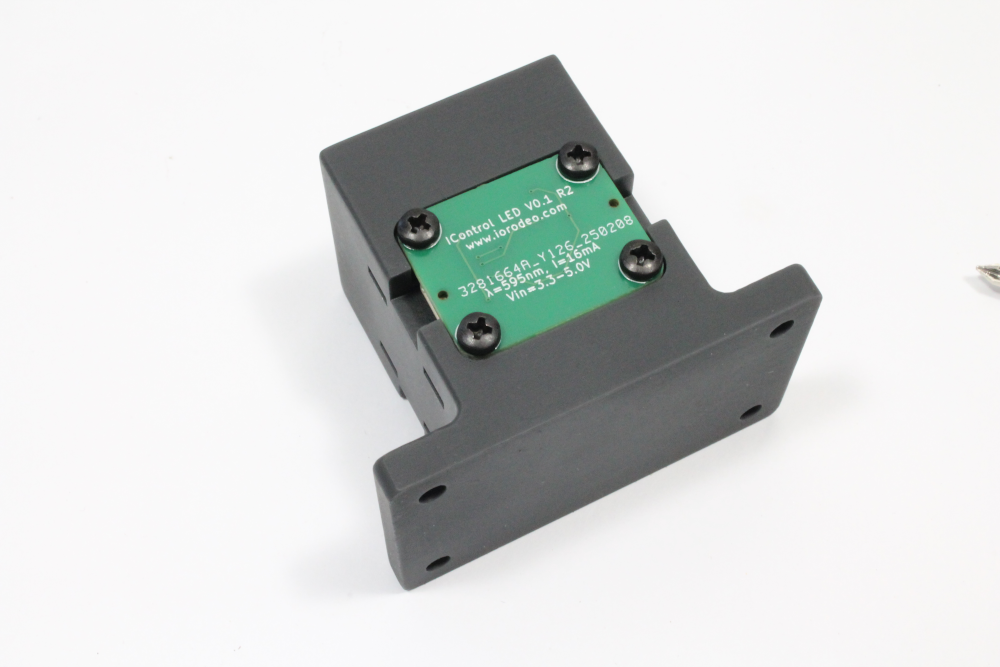
Images of the final Step 1 assembled part
Step 2: PyBadge assembly
- The first step is to attach the battery holder and mini-speaker to the back of the PyBadge. The PyBadge has two spaces indicating where to mount a battery and/or mini-speaker
- Remove the paper backing from the back of the battery holder and stick it to the back of the PyBadge in the indicated "Battery" position
- Insert the connector from the mini speaker into the PyBadge mini connector as shown in the image below. Remove the paper backing from the oval speaker and stick it to the back of the PyBadge in the indicated "Speaker" position
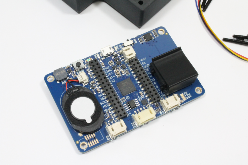
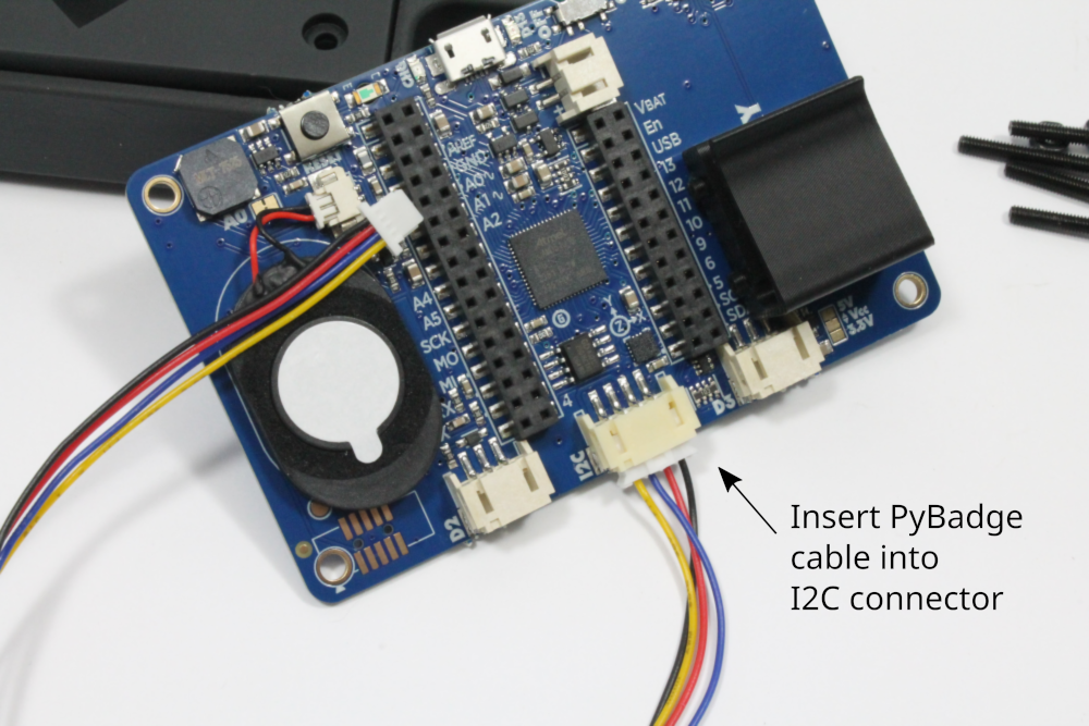
- Insert the large connector on the 200mm PyBadge cable into the I2C connector on the back of the PyBadge
- Place the assembled PyBadge into the PyBadge enclosure
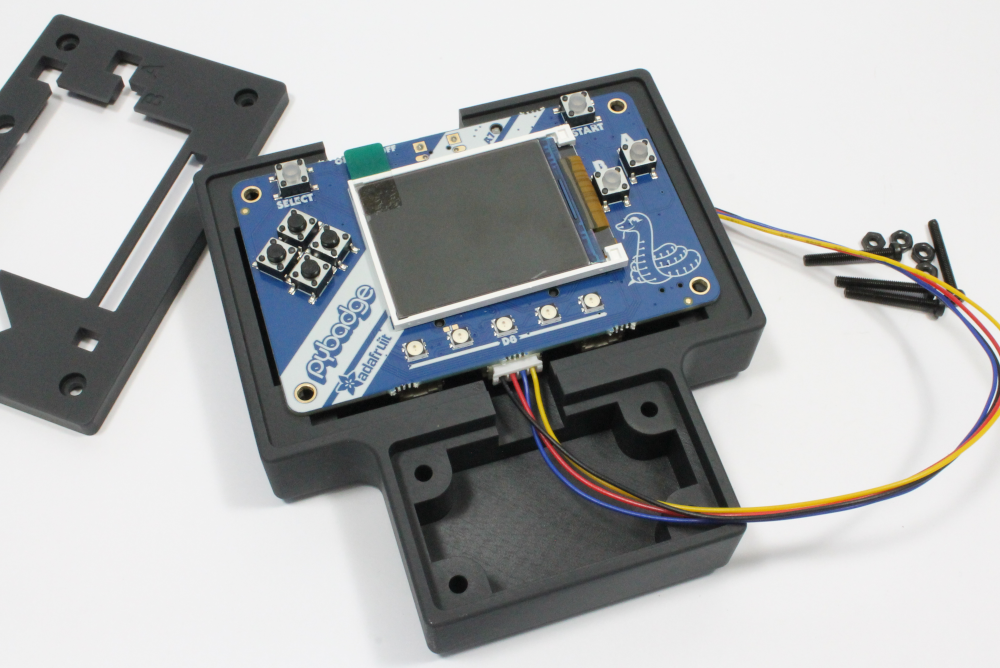
- Place the PyBadge cover over the PyBadge. Place a screw into one of the corner holes and an M2.5 hex nut in the recessed hole on the bottom. Hold the nut in place and use the screwdriver to tighten the screw. Repeat until all 4 corner screws are in place
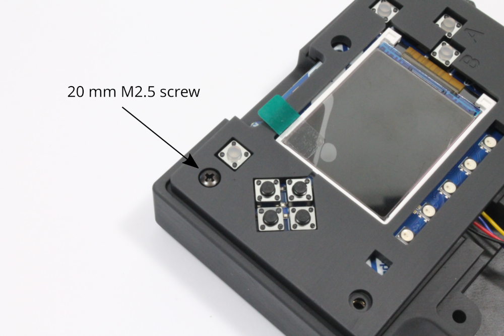
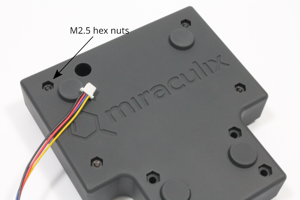
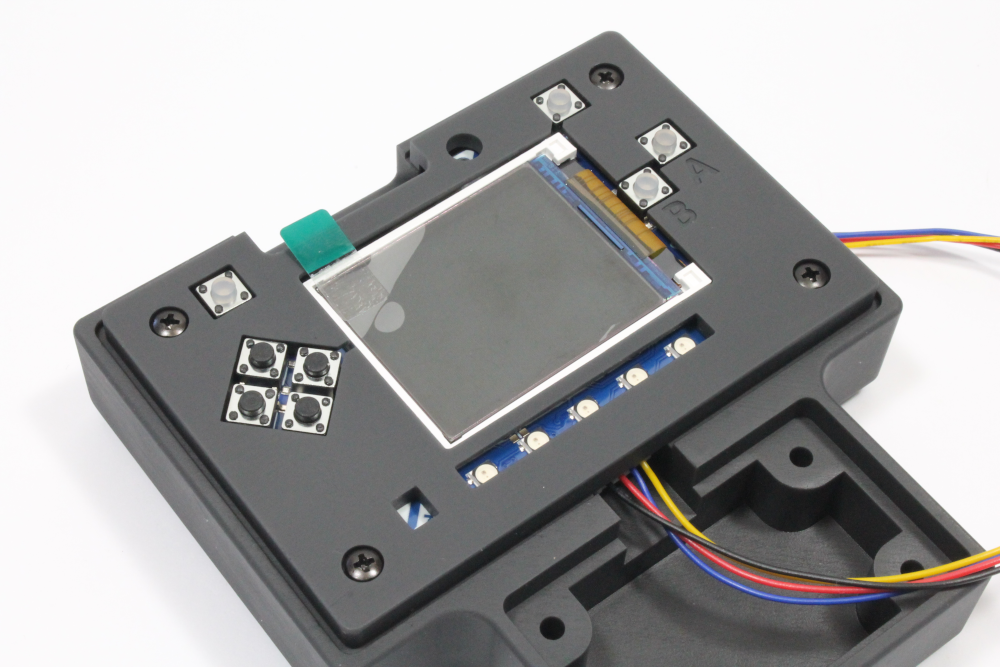
Image of the final Step 2 assembled part
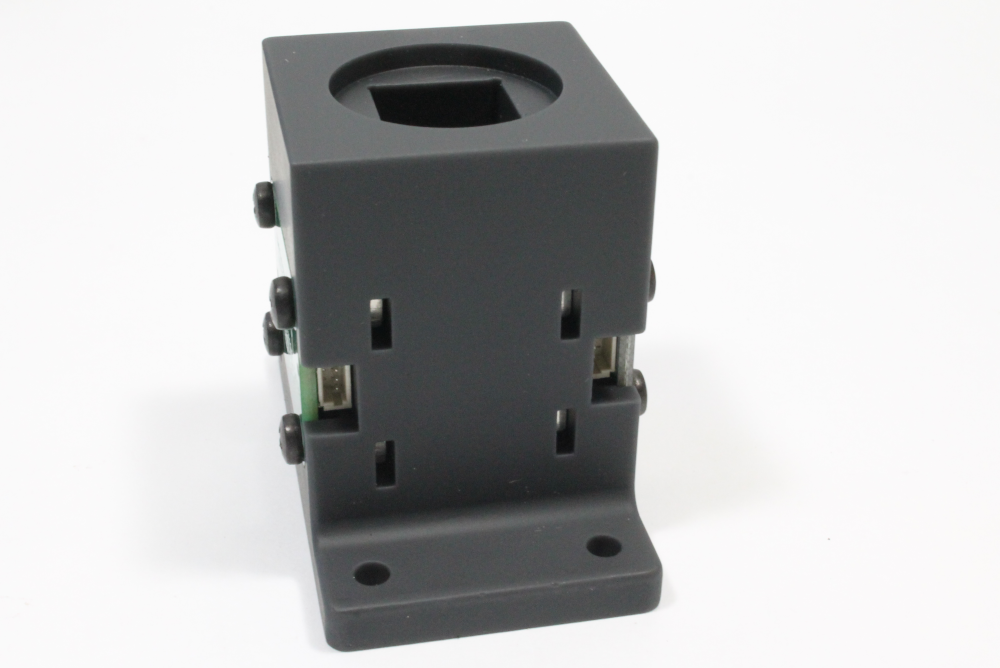
Step 3: Cuvette assembly
- Before mounting the cuvette it can be helpful to do some cable management. Loop the PyBadge cable twice to form a small loop from the additional extra cable
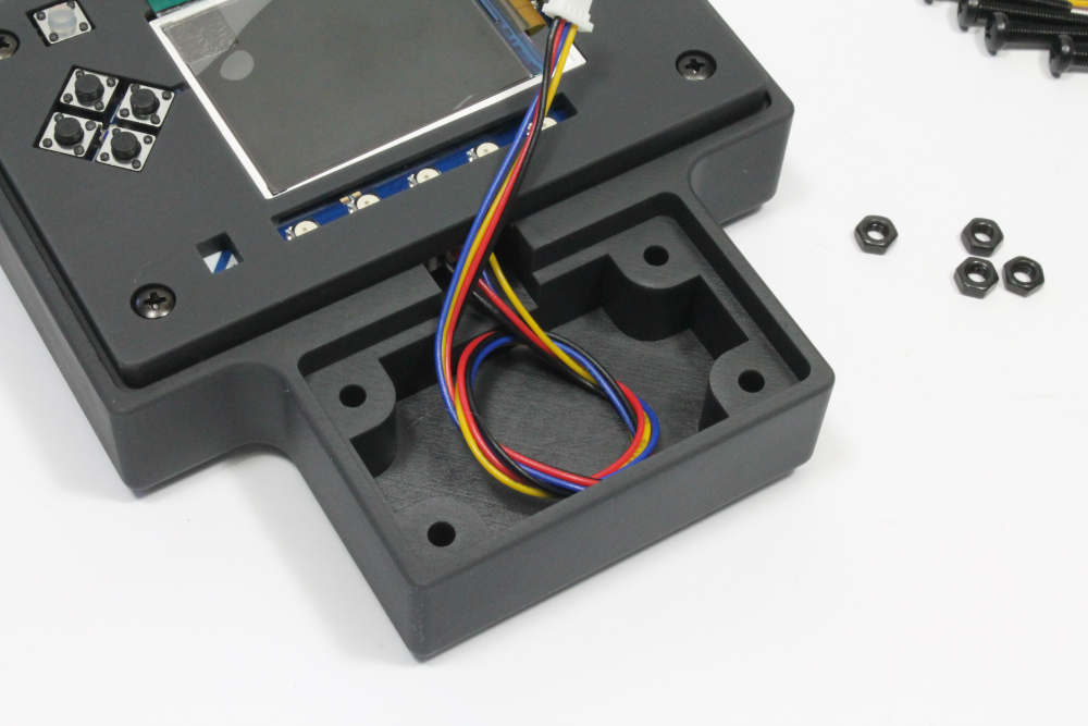
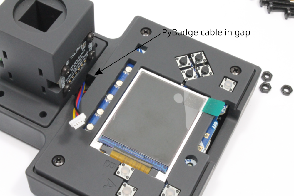
- Next place the cuvette holder onto the enclosure in the orientation shown below with the sensor board facing the PyBadge screen. Also make sure that approx. 1-2 inches of PyBadge cable is sticking out through the gap
- Next, place a 20mm long M3 screws into one of the corner holes and an M3 nut in the recessed hole on the bottom. Hold the nut in place and use the screwdriver to tighten the screw
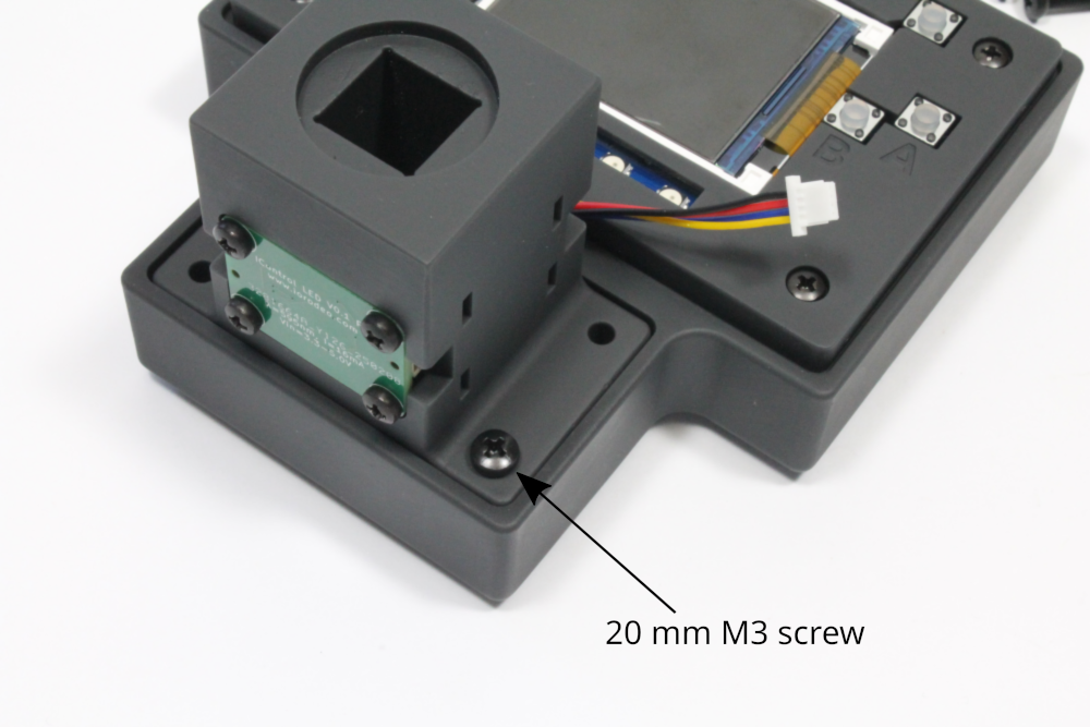
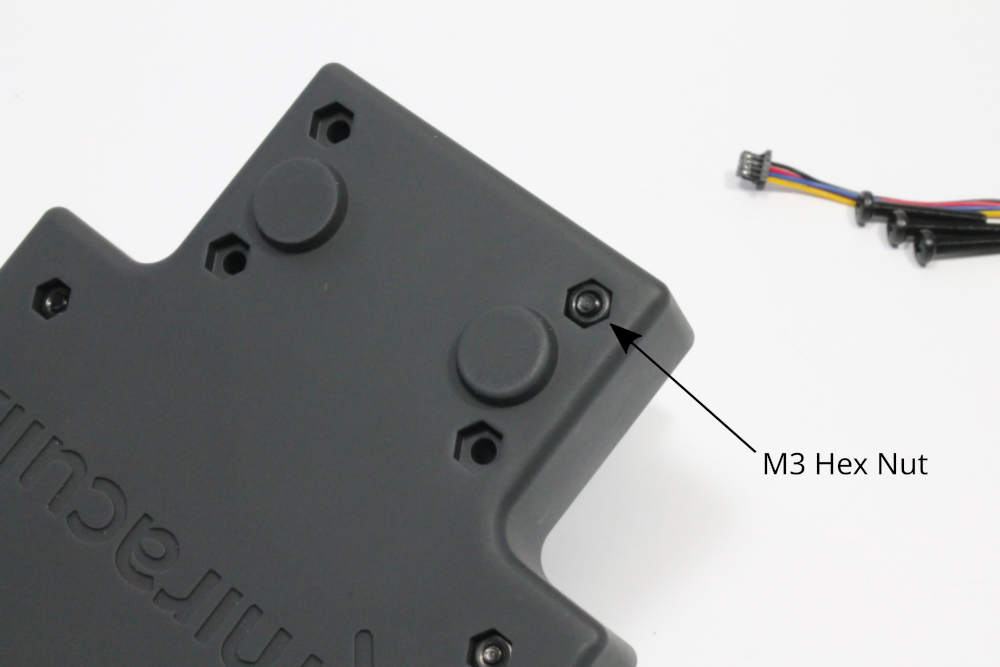
- Repeat until all 4 corner screws are in place
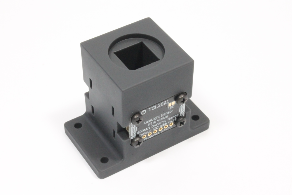
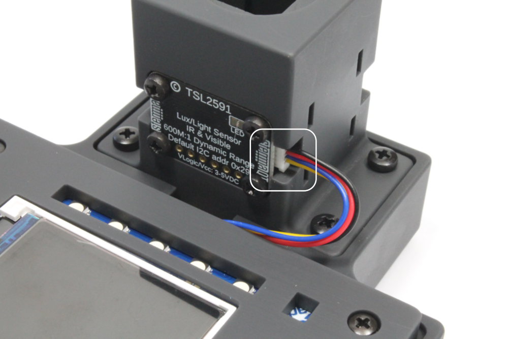
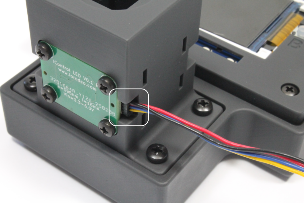
- Connect the PyBadge cable to the connector on the sensor board as shown in the image below
- Connect one end of the 50 mm flexible cable to the right-side connector on the LED board
- Connect the other end of the flexible cable to the left-side connector on the sensor board
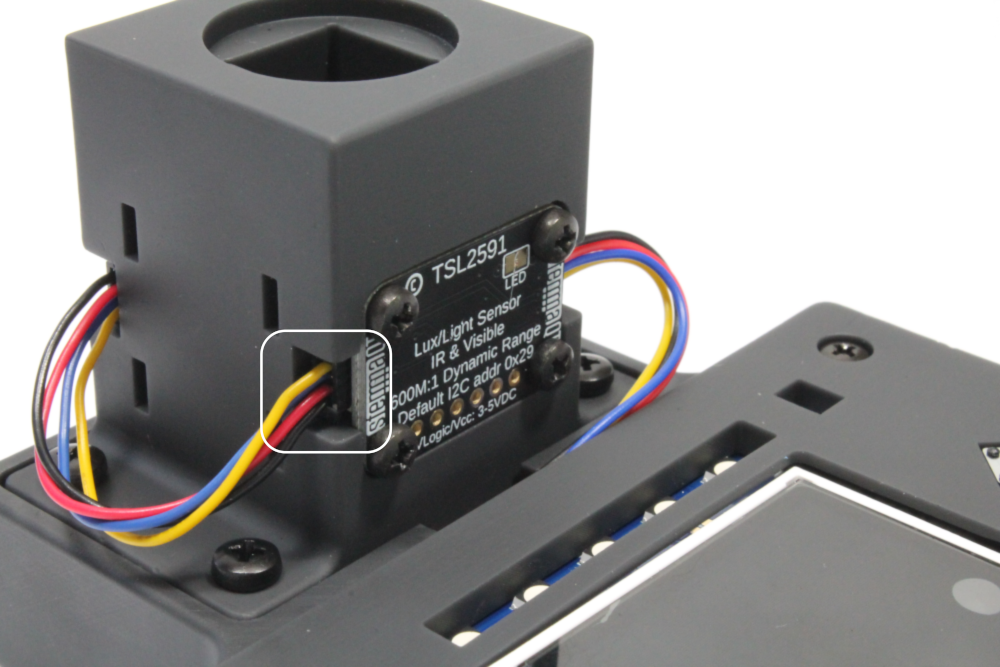
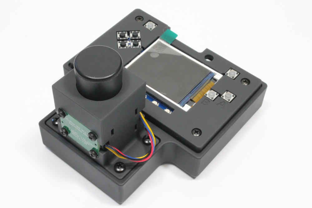
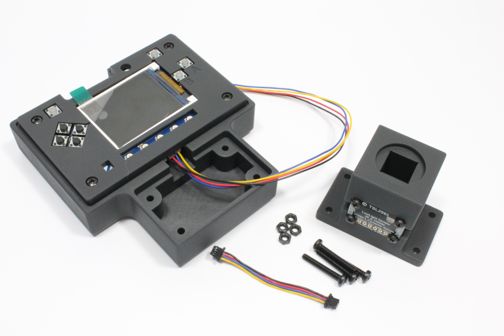
Image of the final assembled photometer
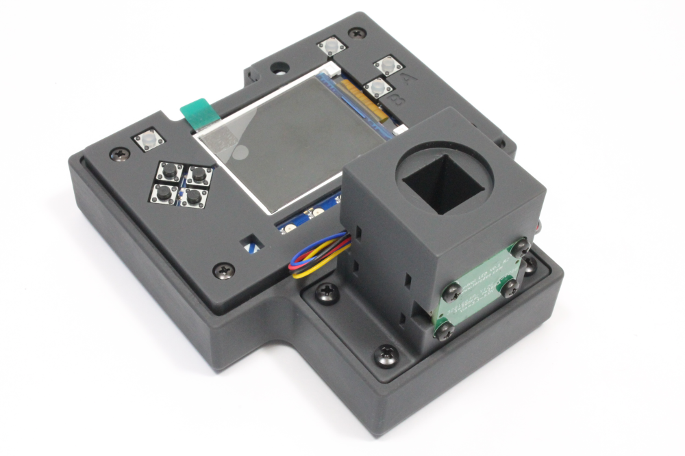
That's it, you have finished assembly! The next steps are programming and adding the QTest calibration data, and you will be ready to start measurements.
Installing a battery
The Miraculix photometer can be powered by USB or a 3.7V lithium ion battery. To use the photometer without a battery, simply plug in the provided USB cable for power.
The kit does not include a lithium battery so you will need to purchase one if you want to use the photometer as a standalone instrument. We have listed some options below.
Recommended battery for the Open Colorimeter (USA)
Recommended battery is the 3.7V 420 mAh Lipo battery. Size: 35mm x 24mm x 5.2mm.
 Adafruit Industries
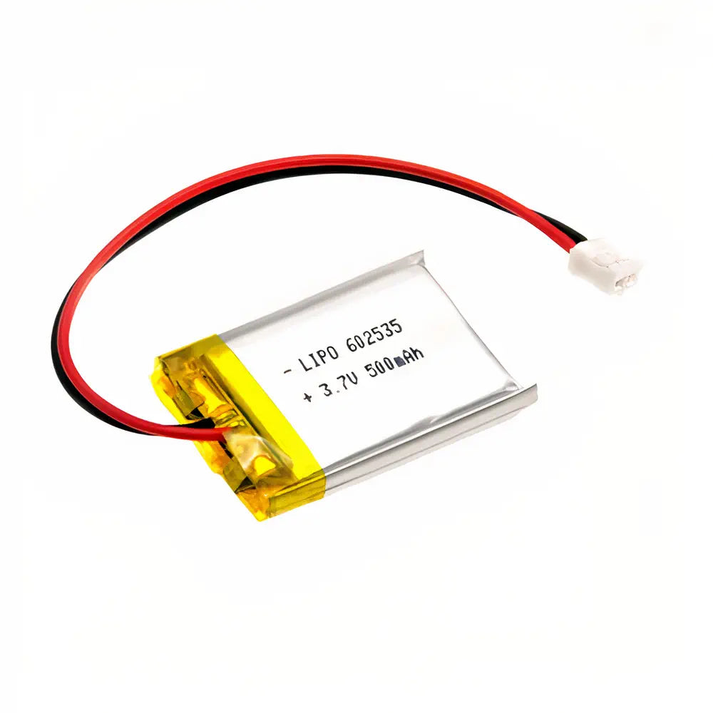
Recommended battery for the Open Colorimeter (EU & UK)
The RobotShop European website ships to the 27 member countries and the UK from its European logistics center based in the Netherlands. Recommended battery is the 3.7V 500 mAh Lipo battery. Size: 35mm x 25mm x 6mm.
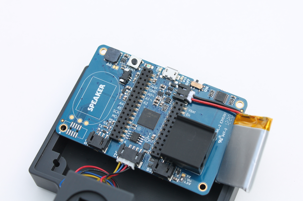
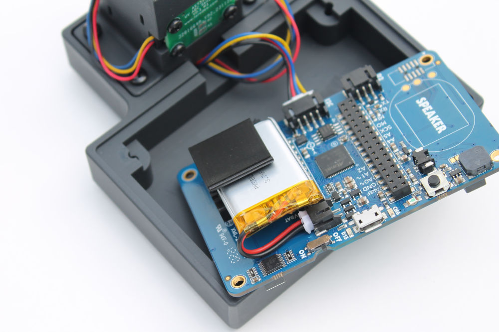
Installation Instructions
Connect the battery and insert into the battery holder as shown in this image.