Rodeostat Muliplexer Kit Assembly
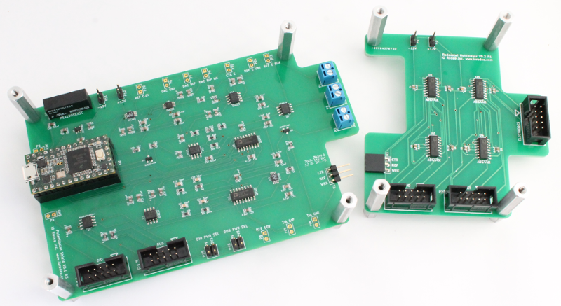
The multiplexer kit is an add-on accessory for the Rodeostat which expands the number of working electrodes that can be used with the Rodeostat from one to seven converting it from a single-channel to a multi-channel potentiostat. In this guide we describe how to connect the multiplexer expansion board to the Rodeostat. For a detailed description on how the multiplexer expansion board works see the Rodeostat Multiplexer Hardware Guide.
Kit contents
The Rodeostat multiplexer kit includes the following items:
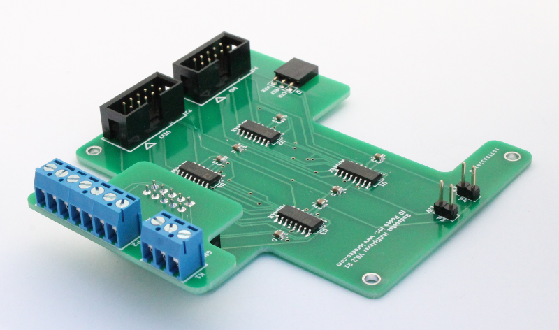
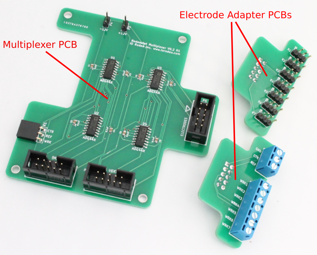
- Multiplexer PCB
- 1 x screw terminal electrode adapter PCB (1 counter, 1 reference, 7 working)
- 1 x seven channel three pin electrode apdater PCB
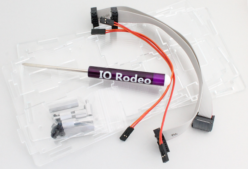
- 2 x 2-pin cables
- 2 x ribbon cables
- Hardware (standoffs and screws)
- Mini screwdriver
- Clear acrylic enclosure for Rodeostat with multiplexer
Attaching to Rodeostat
Below we go over the steps required for attaching the multiplexer expansion board to the Rodeostat.
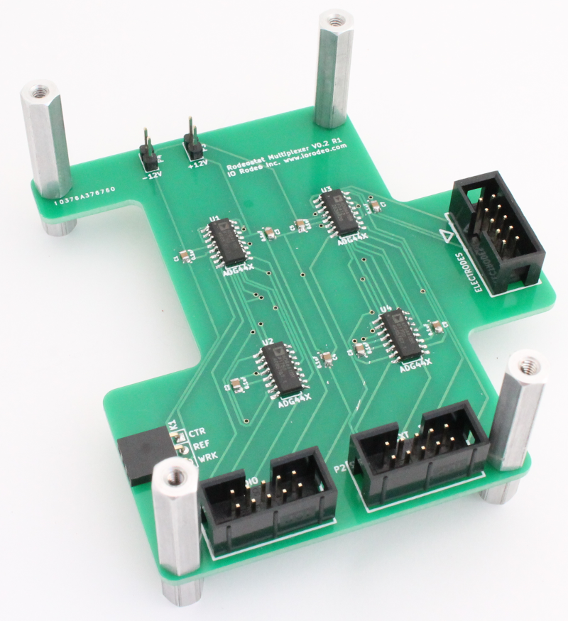
Step 1: Put standoffs onto the Multiplexer board
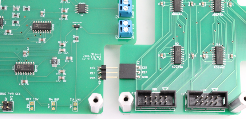
Step 2: Connect multiplexer to the Rodeostat PCB
There is a 3-pin connector on the Rodeostat which will connect the counter, reference and working channels on the Rodeostat to the Multiplexer.
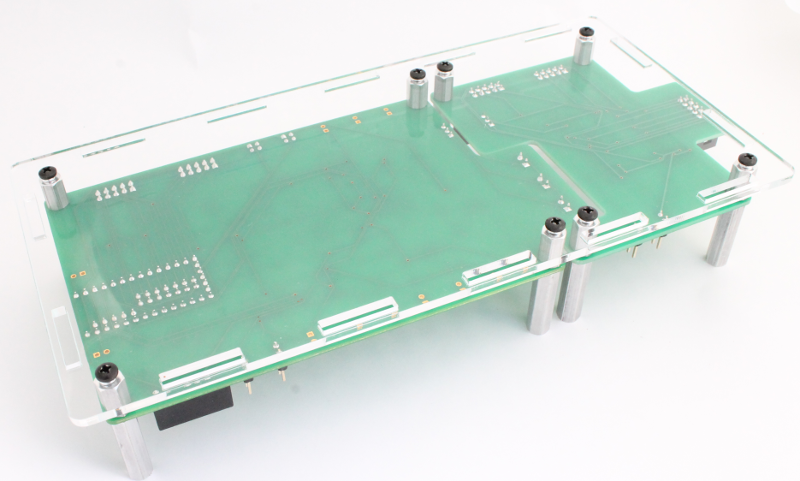
Step 3: Attach to the enclosure base
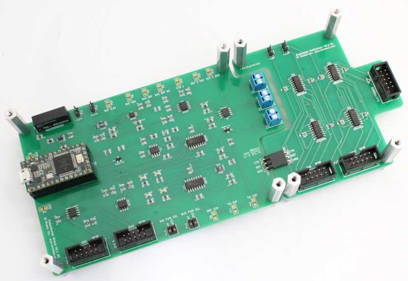
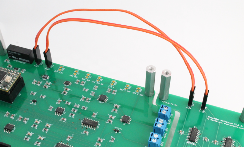
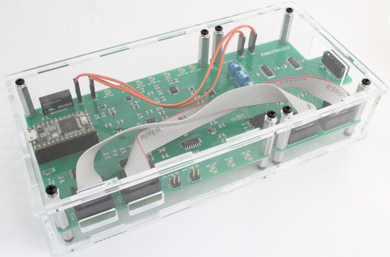
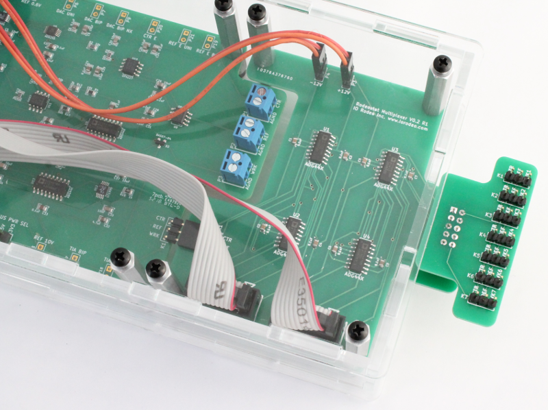
Step 4: Connect +/-12V power using the 2-wire cables
Be sure to connect the +12V on the Rodeostat to the +12V on the multiplexer and the -12V on the Rodeostat to the -12V on the multiplexer. Connecting the power connections incorrectly can damage your multiplexer.
See images below for correct cabling.
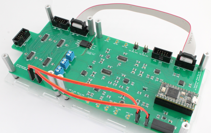
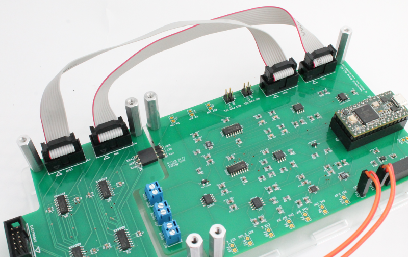
Step 5: Connect using the flat-ribbon cables
The ribbon cables connect the digital control lines from the Rodeostat to the multiplxer.
- Connect the DIO header on the Rodeostat to the DIO header on the multiplexer.
- Connect the BUS header on the Rodeostat to the UEXT header on the multiplexer.
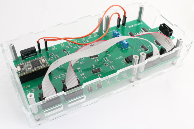
Step 6: Finish assembly of the enclosure
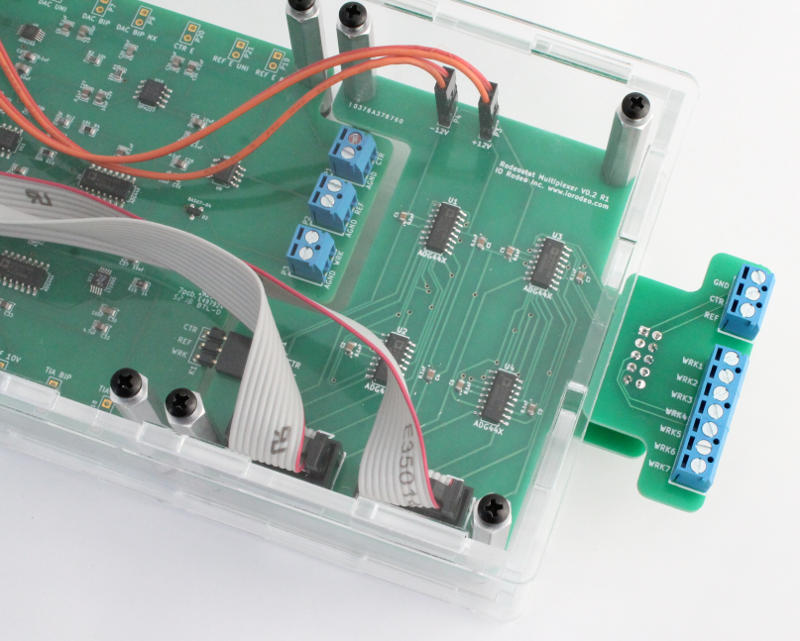
Step 7: Attach an electrode adapter PCB
The multiplexer comes with two different electrode adapter PCBs for connecting to the test electrodes.
-
The screw terminal electrode adapter PCB is for use with standard alligator clip style cables or any electrode which can be used with a screw terminal.
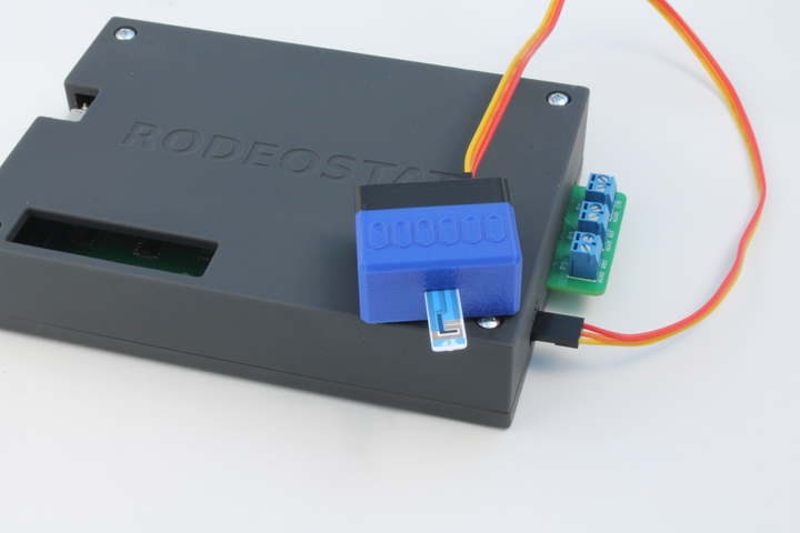
-
The seven channel 3-pin electrode adapter PCB is for use IO Rodeo's screen printed electrode adapters.
The electrode adapter PCBs connect to the Rodeostat via the 5x2 shrouded header at the top of the multiplexer which extends outside of the enclosure.
The screw terminal and seven channel 3-pin electrode adapters are shown connected to the multiplexer in the images below.
Comments ()