New Rodeostat Enclosure Design
Design of a new 3D-printed enclosure for the Rodeostat using FreeCAD
The focus of this newsletter is the design of a new enclosure for our open source Rodeostat. Currently, the Rodeostat is sold with a simple enclosure which is laser cut from clear acrylic. This week we designed a new enclosure which can be 3D printed. We plan to manufacture prototypes of the new enclosure in black SLA resin. This will make a much sturdier enclosure that users can assemble even more easily than the current design. We will also make the design files available so that users can print and modify their own enclosures if they wish.
Design with FreeCAD
We have been using FreeCAD for 3D hardware designs for a few years now and really enjoy working with it. It is an open-source parametric 3D modeler with a very active and helpful user community. It is multi-platform supporting Windows, Linux and Mac. It has a built-in Python interpreter and is designed from the ground up to be deeply customizable. There are loads of useful community developed external workbenches. In this project we used the KiCad StepUp workbench to import a 3D model of Rodeostat PCB from KiCad and the A2plus Workbench to create an assembly of the complete enclosure including PCB and fasteners. Finally, there are tons of great FreeCAD tutorials online to help you get started and advance your skills.
Enclosure components
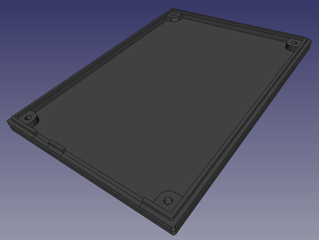
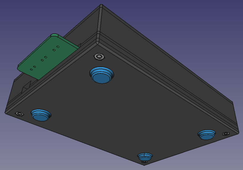
The enclosure consists of two components - a base and top. Shown below is the base. There are holes for mounting the PCB and cutouts for the screw terminals and 3-pin header. On the underside of the base corresponding to each screw holes is a hexagonal pocket for placing a nut (not shown).
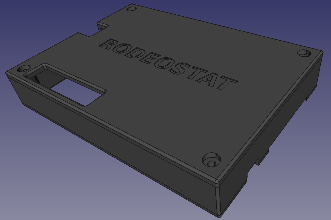
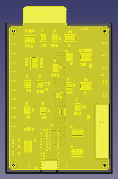
The top has the same corresponding corner holes for mounting the PCB with recessed pockets for the screw heads. There are cutouts for the USB connection and expansion cables and we added a "RODEOSTAT" logo.
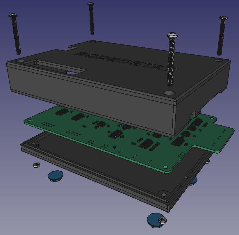
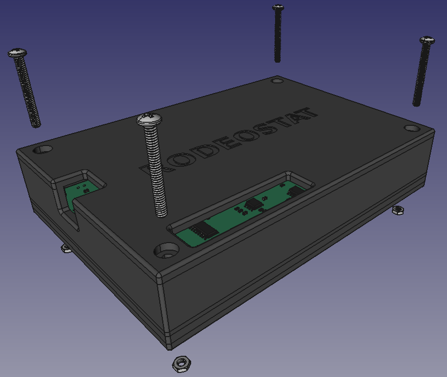
Below is an exploded view of all the components, which we made using the A2Plus workbench. You can see the two parts of the enclosure plus the Rodeostat PCB and hardware (nuts, screws and rubber feet).
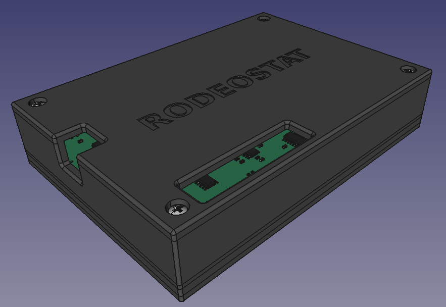
The two parts fit together snugly with the Rodeostat PCB sandwiched between the top and base of the enclosure.
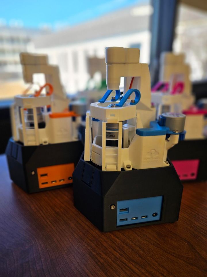
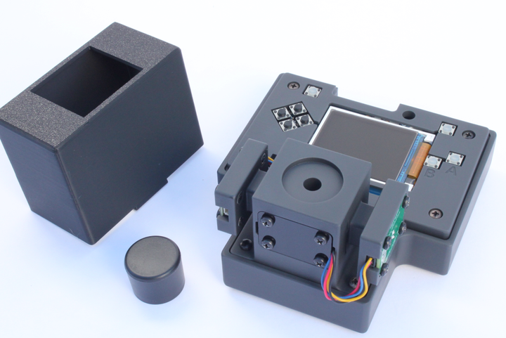
Below are some images of the final assembly

Rodeostat Enclosure Details
- Dimensions: 95.7mm width x 133.8mm length x 28.2mm height
- Two 3D-printed parts (base and top)
- Recessed pockets for hardware
- Cutouts for cables and adapters
- Hardware: 4 x 1" long 4-40 screws and 4 x 4-40 nuts
Bookmarks
 IO Rodeo


Comments ()