Open water level sensor kit
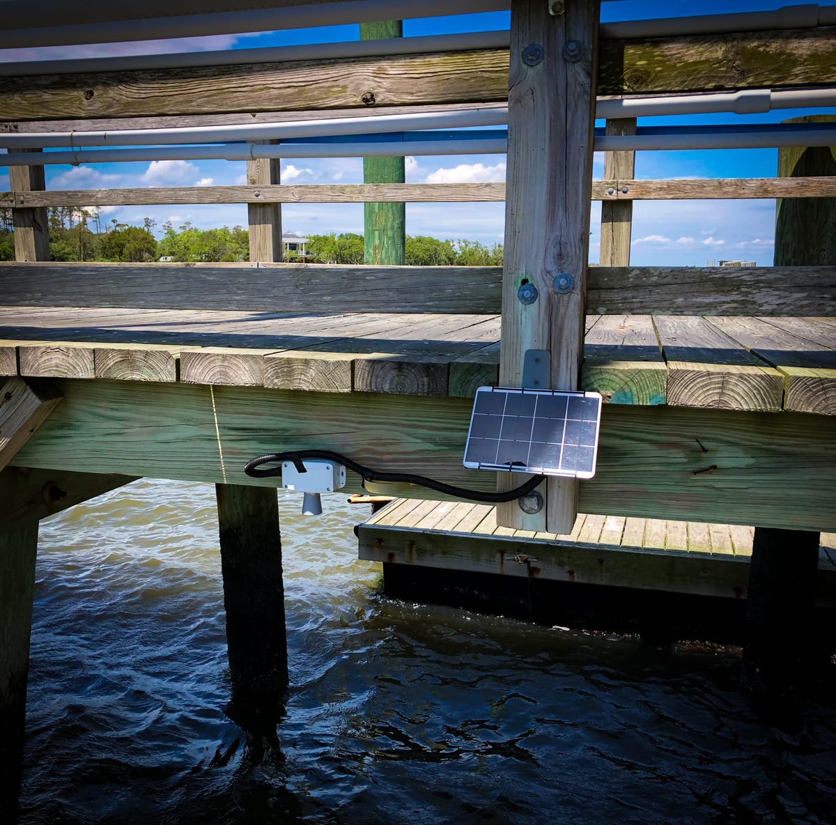
This tutorial covers the assembly of an open water level sensor kit. The kit is developed in collaboration with the COAST Lab with a shared goal of making open hardware instruments for coastal science more accessible and affordable. For the most up-to-date BOM, project developments and more follow the project at https://github.com/COAST-Lab/Open-Water-Level-SK-15-Enclosure. Additional background about the project can be found in the Coastal Science guest blog posts.
Kit Contents
The Open Water Level Sensor kit includes the following parts:
- Waterproof, outdoor electronics enclosure
- Polycase SK-15 enclosure
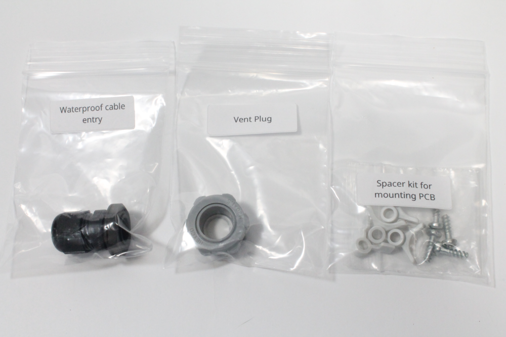
- Polycase SK-15 PCB spacer kit
- Polycase enclosure mounting kit
- Vent plug
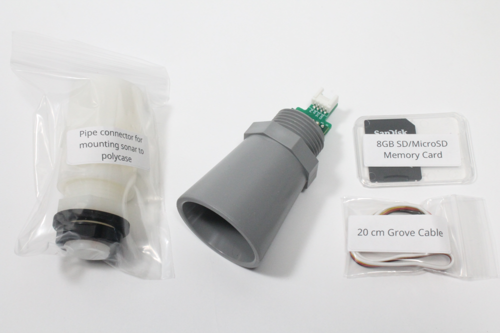
- Ultrasonic distance sensor
- XL-MaxSonar-WRMA1 distance sensor with pre-soldered adapter
- MaxSonar pipe connector
- 20 cm grove cable
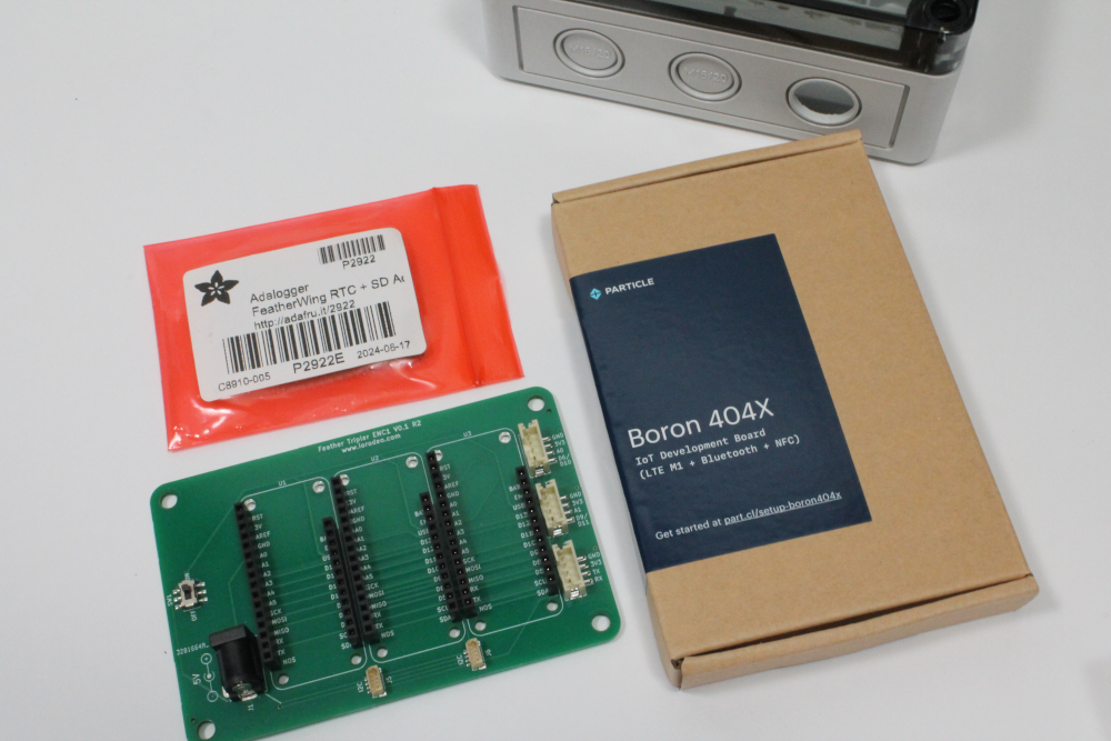
- Electronics
- Feather Tripler PCB
- Adalogger FeatherWing
- BORON LTE CAT-M1 with antenna
- 8 GB microSD card
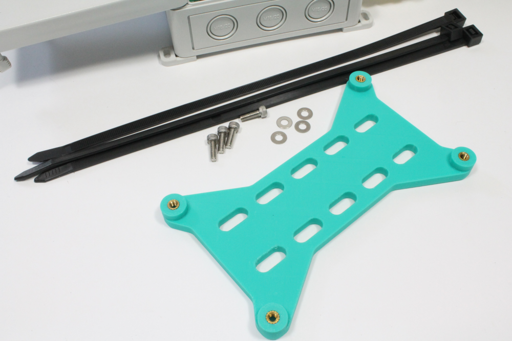
- Outdoor enclosure mounting hardware
- 3D-printed enclosure mount
- Wide zip ties
- 10-32 socket screws and washers
- Solar power system and waterproof entry
- Voltaic 5 Watt 5 Volt 35Wh Solar System
- Waterproof cable entry (cable gland)
Additional required tools not included in the kit
- Hammer for the enclosure mounting kit (Step 1)
- Philips screwdriver for mounting the Feather Tripler PCB (Step 3)
- Hex wrench for 10-32 socket screws - for the outdoor enclosure mounting plate (Step 4)
- Flat blade screwdriver for the Polycase lid (Step 6)
Assembly Instructions
Step-by-step guide for the water level sensor kit
Step One - Preparing the Polycase Enclosure
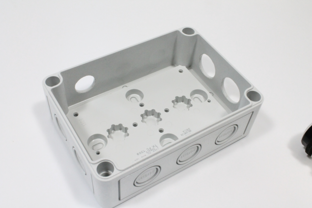
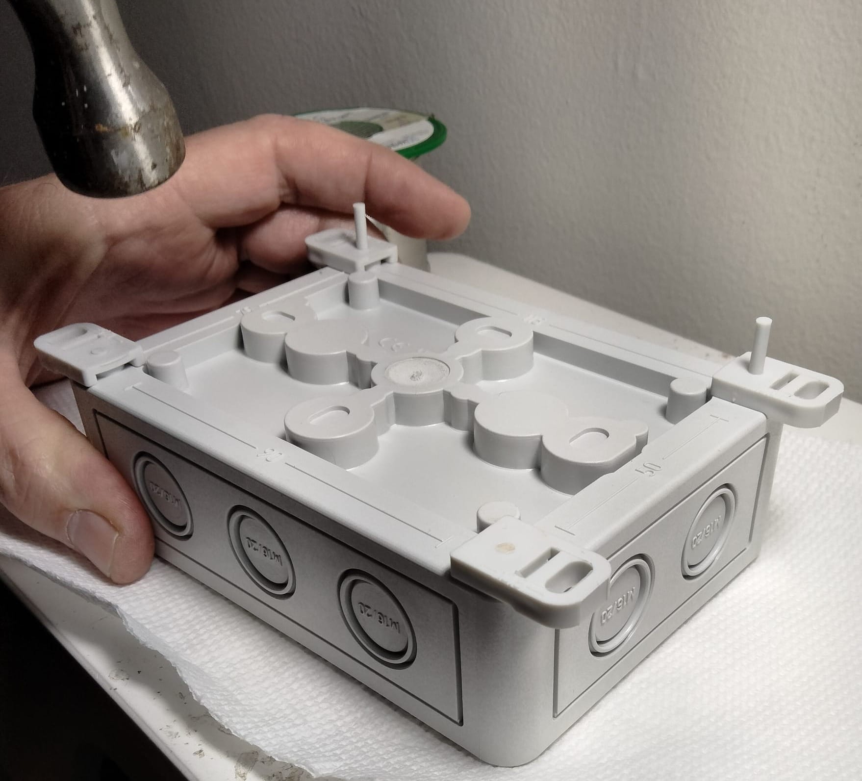
i) Attach the 4 mounting feet to the base of the enclosure using a hammer to gently tap the feet into place
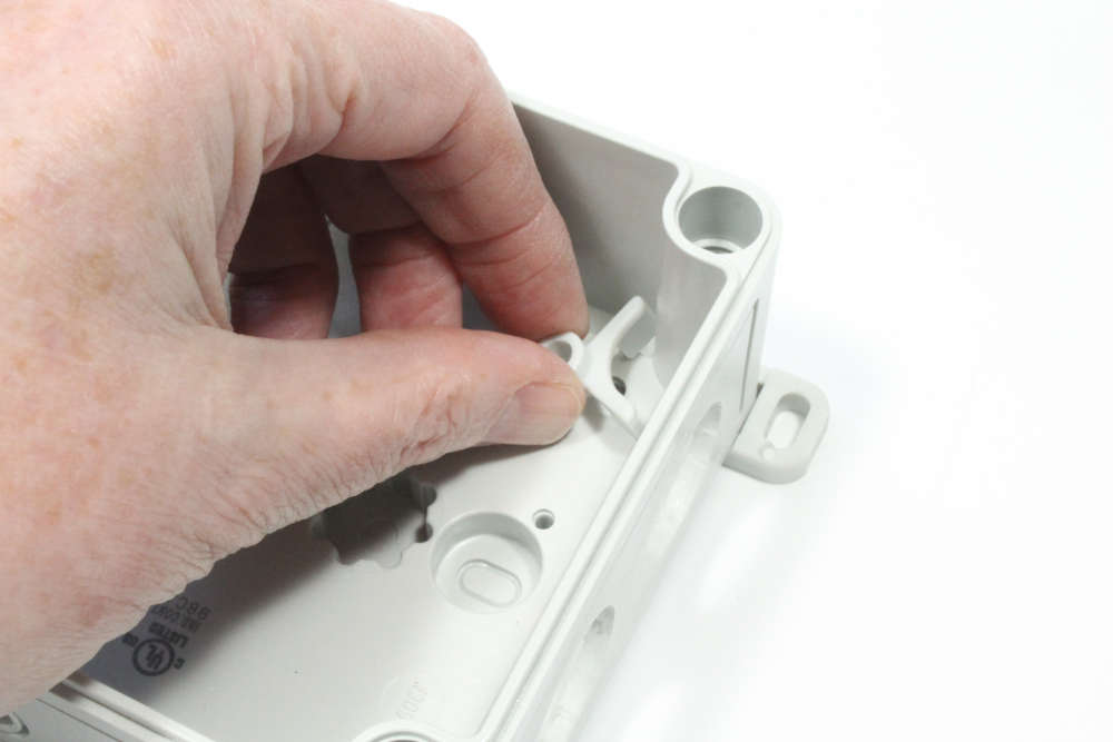
ii) Insert the 4 PCB mounting parts into the corners of the enclosure. Press them firmly into place, one in each corner.
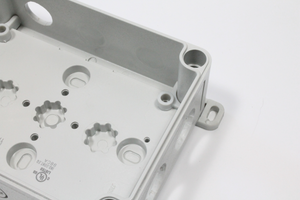
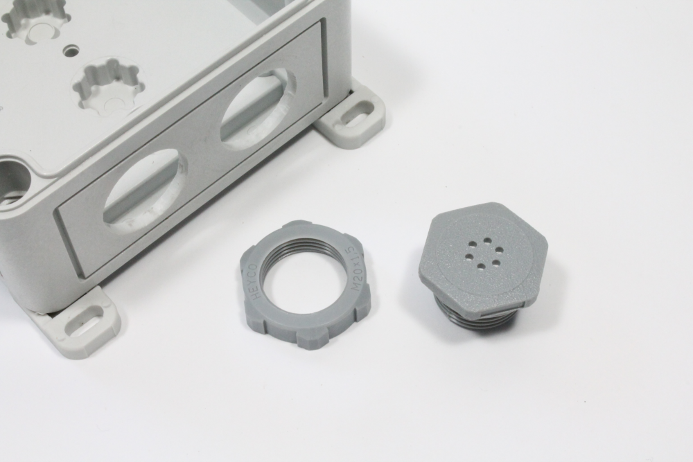
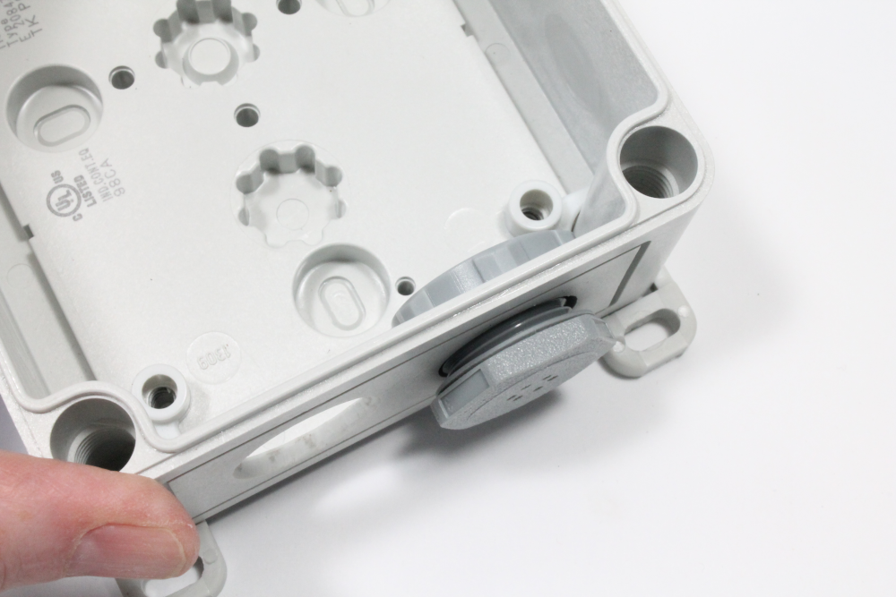
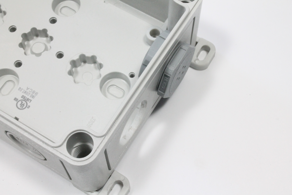
iii) Unscrew to separate the two parts of the vent plug. Place the vent part into the bottom right knockout with the plastic ring inside the enclosure. Screw the parts back together again so that the vent plug is facing out of the enclosure as shown in the images below.
Step 2 - Mounting the MaxSonar ultrasonic distance sensor
i) Attach the 20 cm cable to the sonar sensor
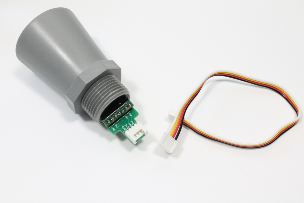
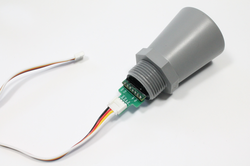
ii) Take the assembled pipe connector out of its bag and unscrew to separate into the 3 individual parts shown below
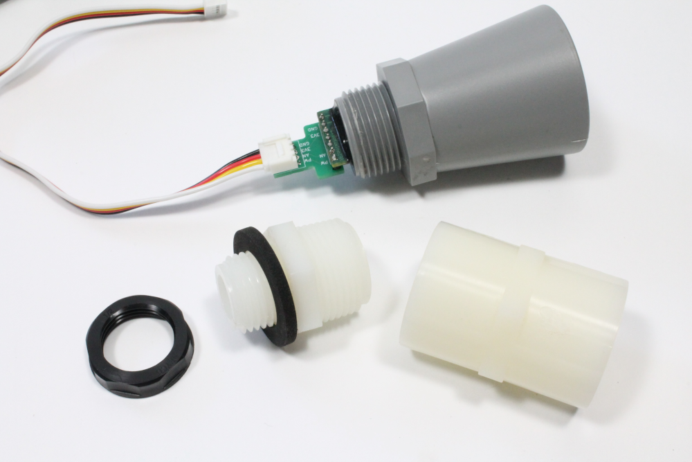
iii) Fit the extender pipe over the cable and adapter and screw directly onto the max sonar sensor. Fold the cable into the extender pipe leaving approx. 1-2 inches of cable sticking out
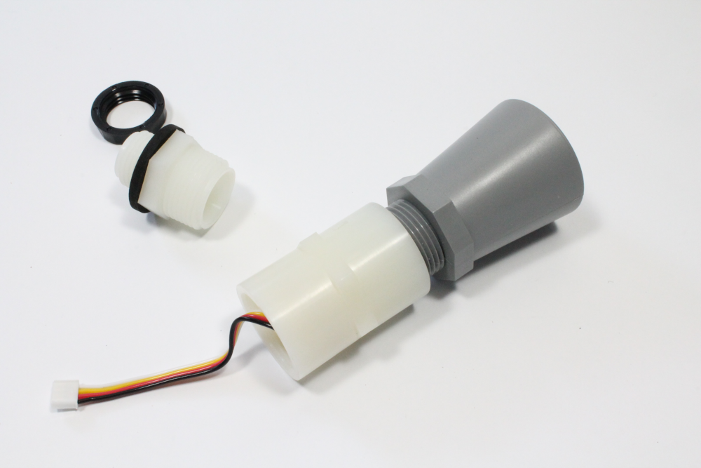
iv) Next fit the reducer over the cable and screw into the pipe connector.
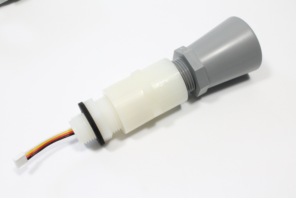
v) Fit the assembled sensor into the enclosure placing the black locknut inside the enclosure to secure the sensor in place.
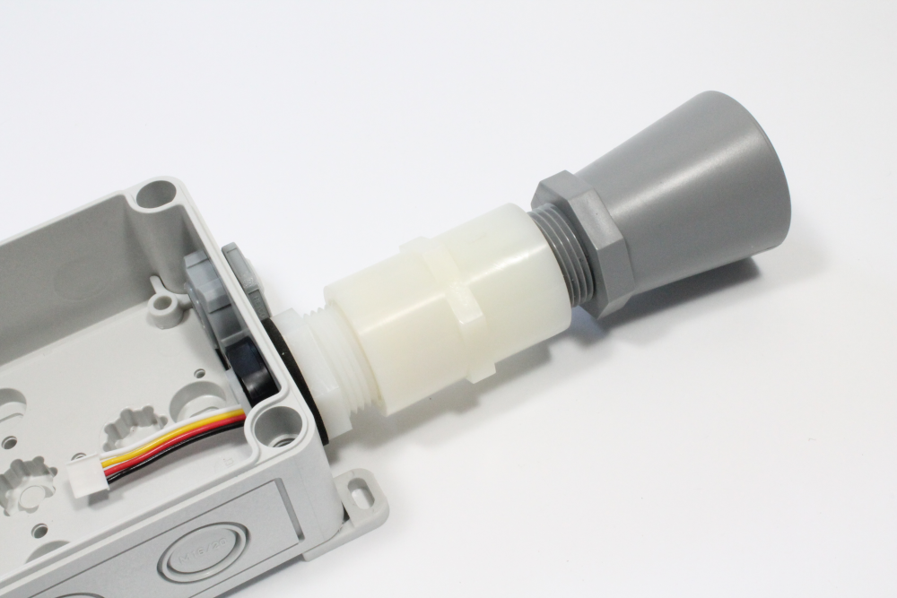
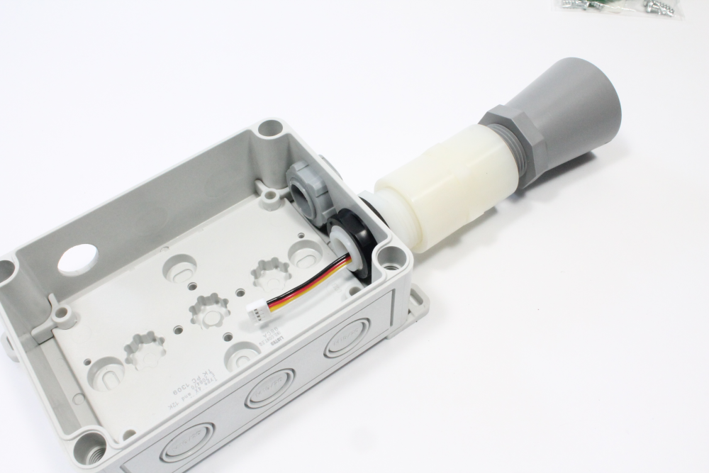
Step 3 - Mounting the electronics in the enclosure
i) Mount the Feather Tripler PCB into the enclosure using the 4 mounting screws. Tighten down with the screwdriver to secure in place
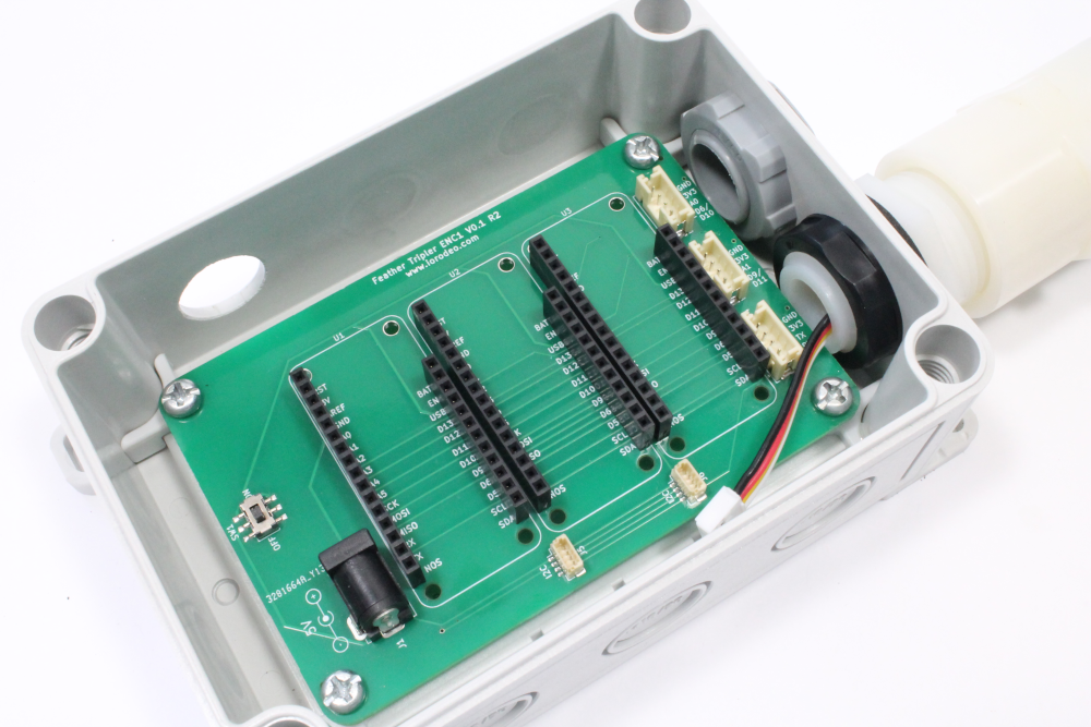
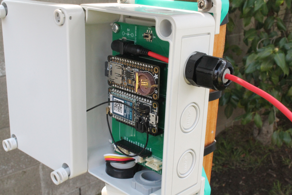
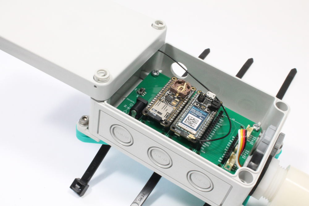
ii) Connect the cable from the MaxSonar to the middle JST PH 4-pin connector (J3). Use the image below to verify the cable is inserted in the correct orientation. Next, insert the micro SD card into the SD card socket on the Adalogger and insert both the Adalogger FeatherWing and Boron onto the PCB.
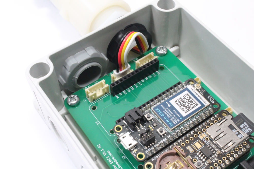
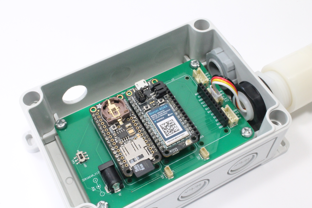
iii) Remove the backing from the antenna and stick it to the underside of the lid.
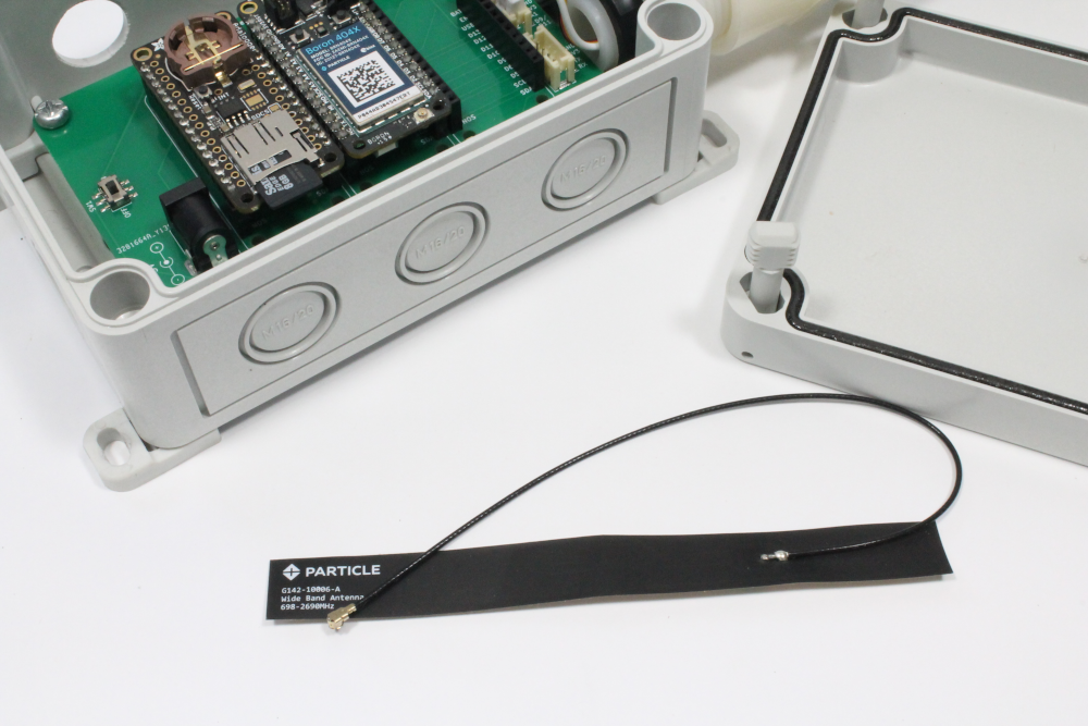
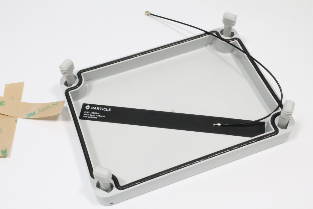
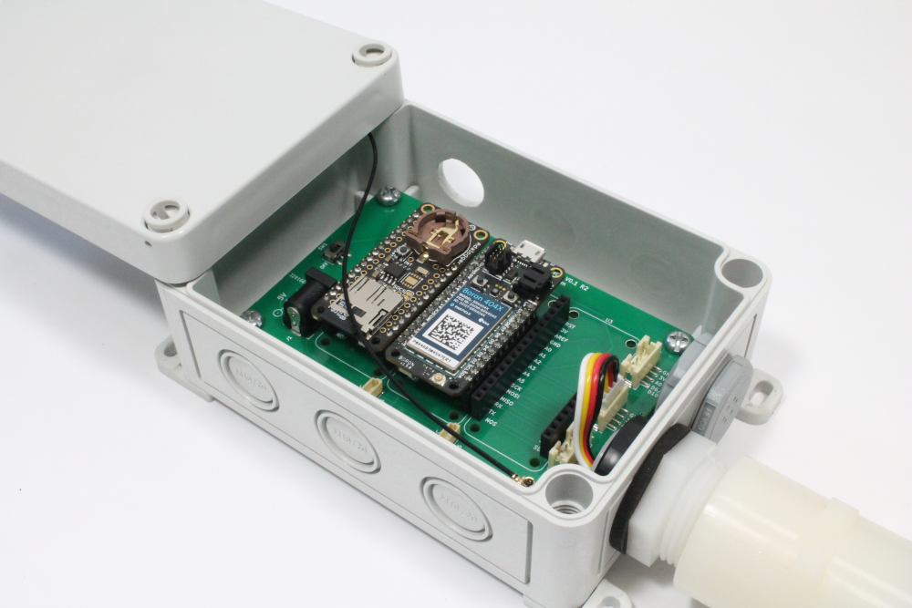
iv) Push the the antenna cable connector into the corresponding header on the Boron to connect the antenna.
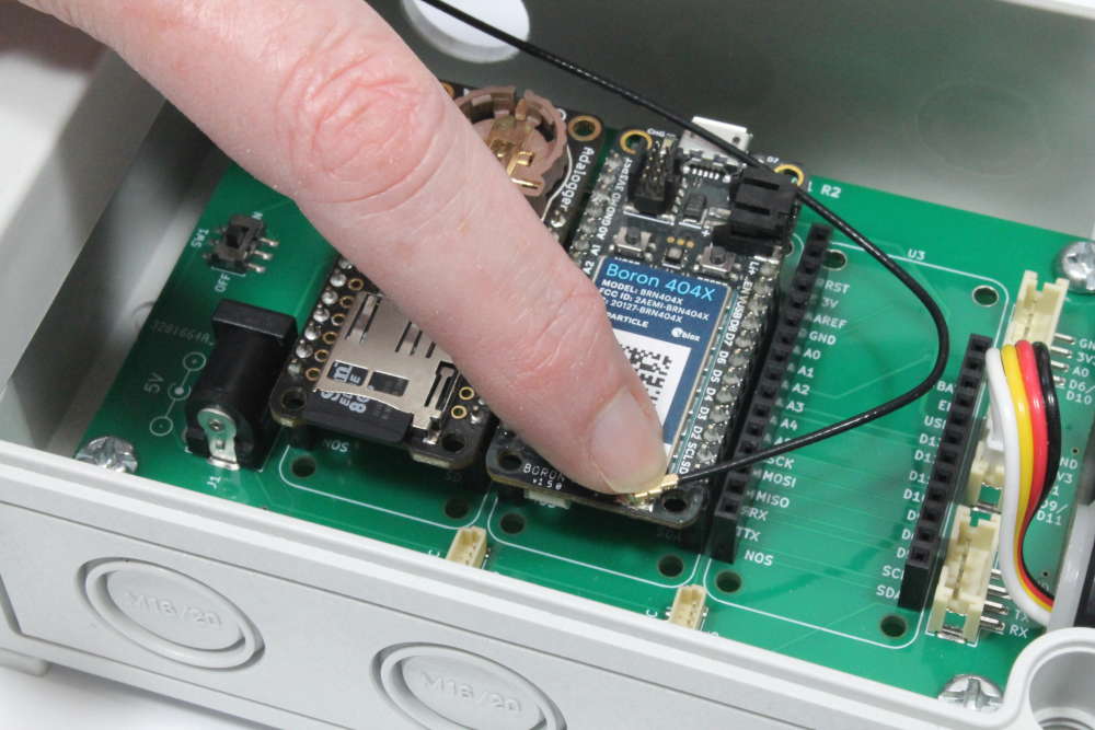
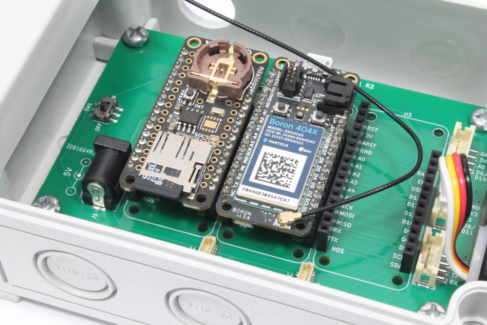
Step 4 - Attaching the enclosure mounting hardware
i) Thread 3 of the cable ties through the mount as shown here
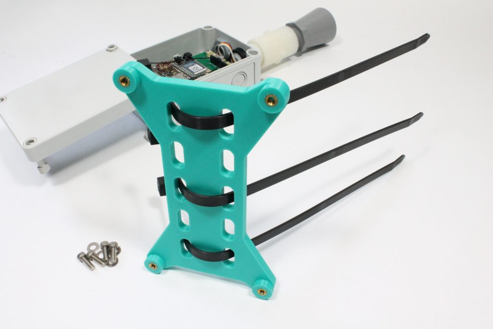
ii) Place a washer and socket head screw through one of the mounting feet attached in Step 1. Using the hex wrench, screw the hardware into one of the brass inserts on the 3D-printed mount. Repeat this for the other 3 mounting feet on the enclosure. Use the hex wrench to tighten down. Your final assembled part should look similar to the images below.
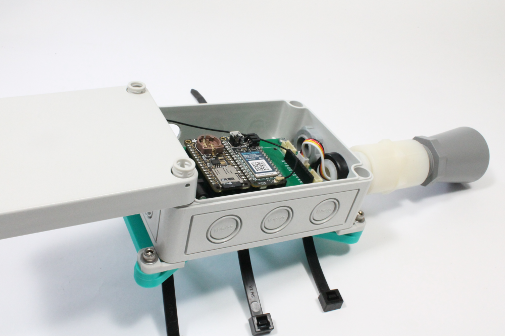
Step 5 - Prepare the solar power system
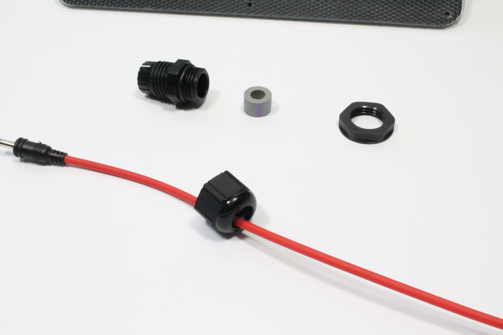
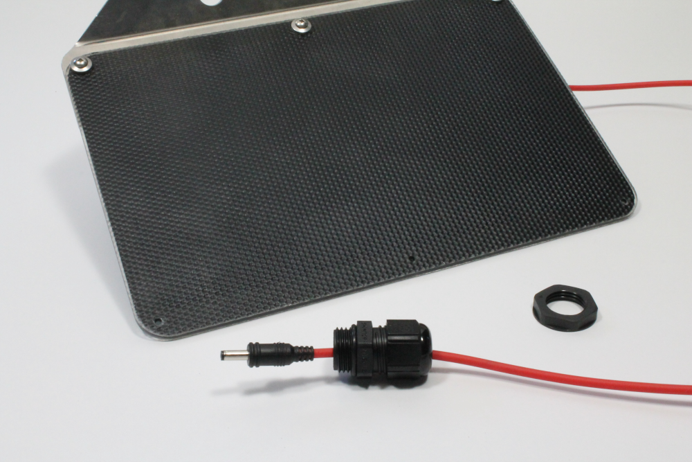
i) Take the waterproof cable entry out of its bag and unscrew to separate into the 3 individual parts shown below. Push the rubber ring out of the main part.
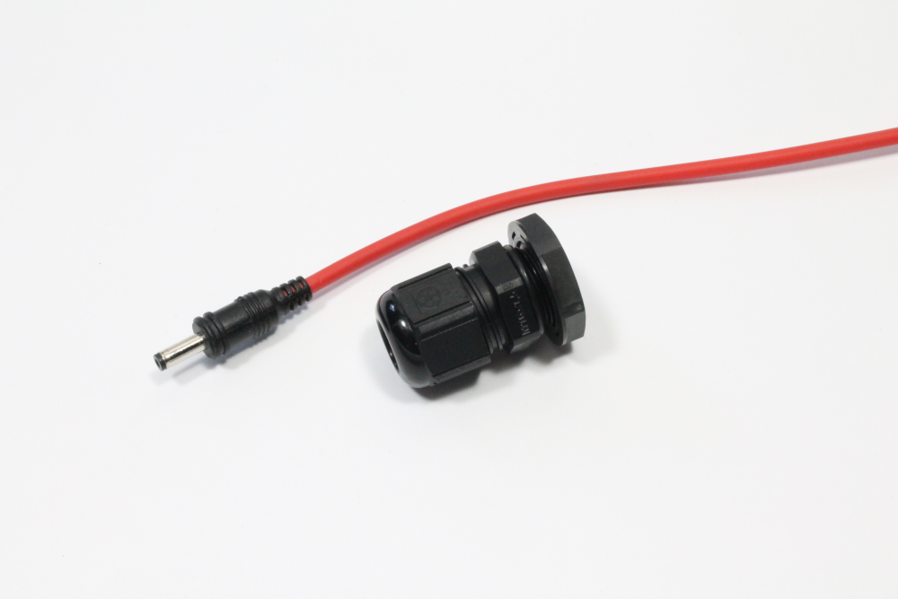
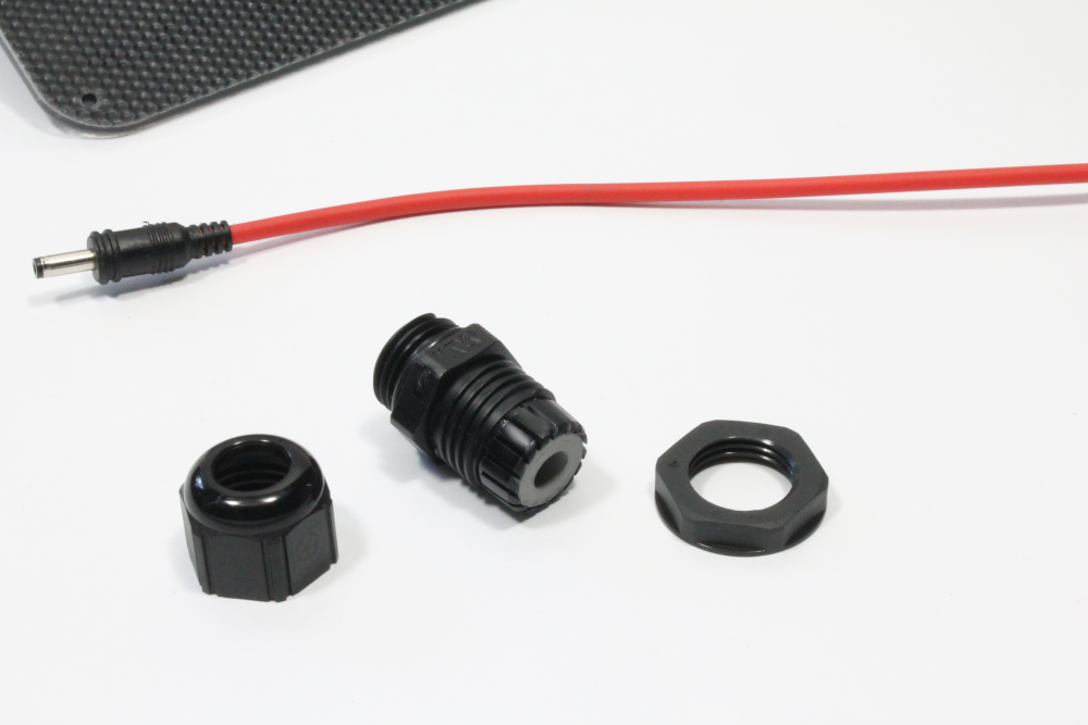
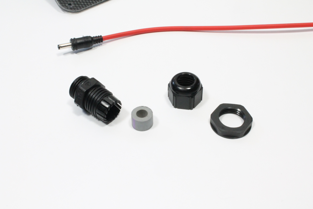
ii) Take the end of the solar system power cable and pass it through the "cap" end in the orientation shown below
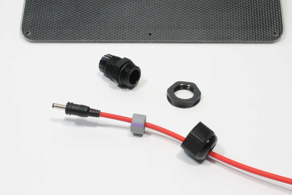
iii) Next, work the rubber gasket onto the power cable. This can be a tight fit over the plug, so gently push/slide the rubber gasket until it goes onto the cable
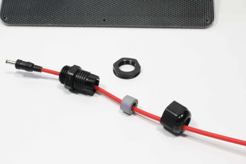
iv) Next, pass the main part onto the cable and re-insert the rubber gasket back in place
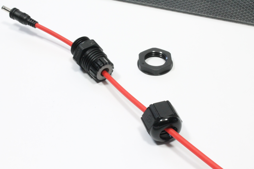
v) Screw these two parts back together again. The lock nut will be used in the next step, so set this aside for now.
Step 6 - Mounting the sensor and connecting power
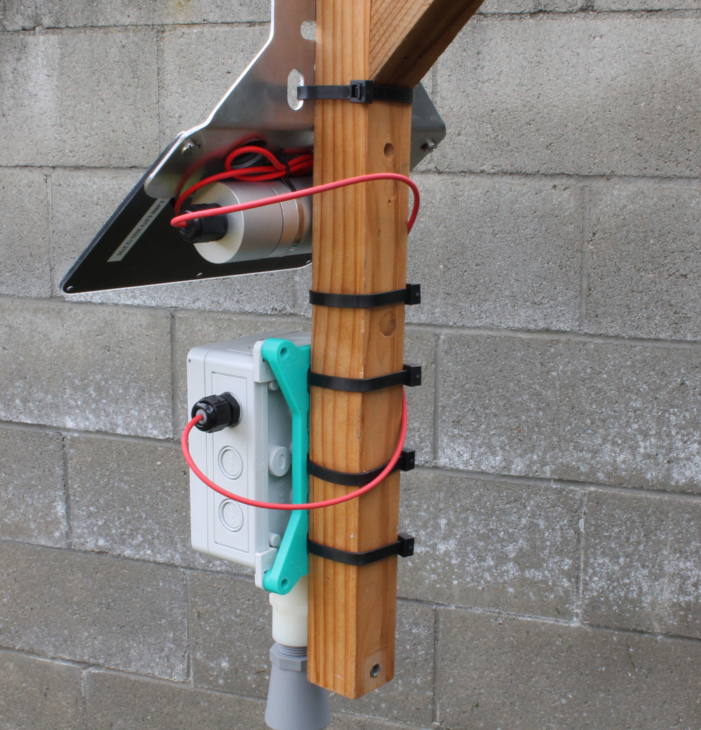
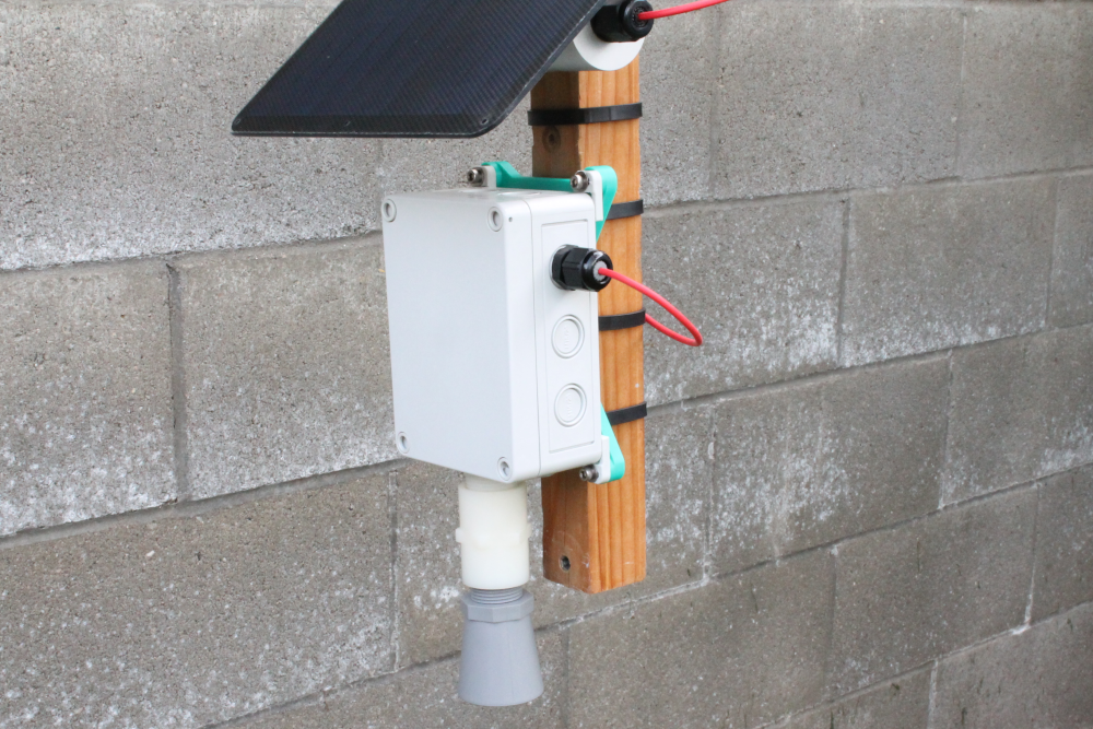
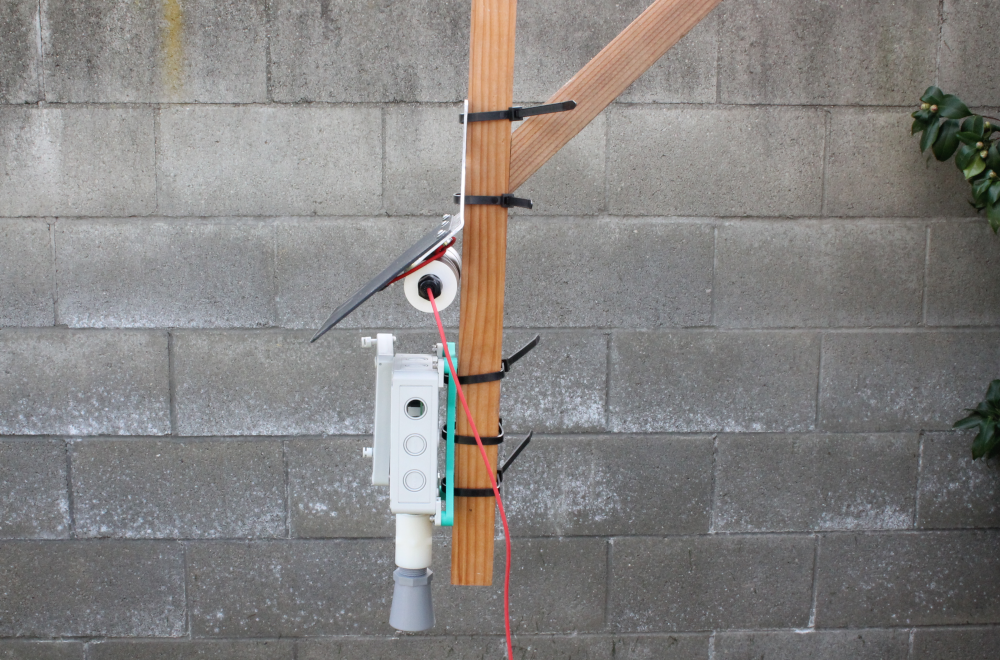
i) Using the zipties, mount the enclosure and solar system as shown in this example. Make sure everything is tightened down securely before moving to the next step.
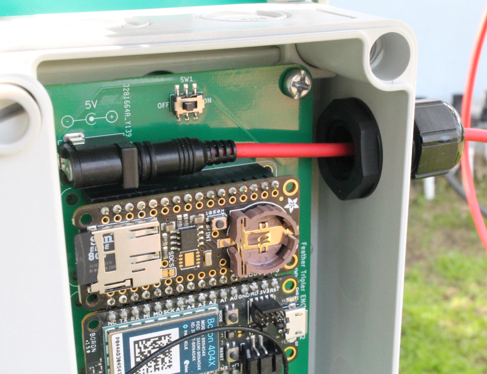
ii) Place the lock-nut from the previous step 5 into the enclosure and pass the end of the power supply cable through the enclosure knockout and lock-nut into the DC jack plug on the Feather Tripler. Once you have the power cable situated, tighten down the lock-nut inside the enclosure and the waterproof cable entry on the other side. The cable should be tightly gripped in place.
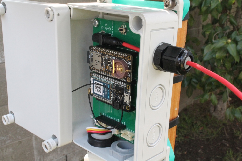
iv) Finally, secure the Polycase lid in place over the enclosure. Screw down using the flat blade screwdriver.
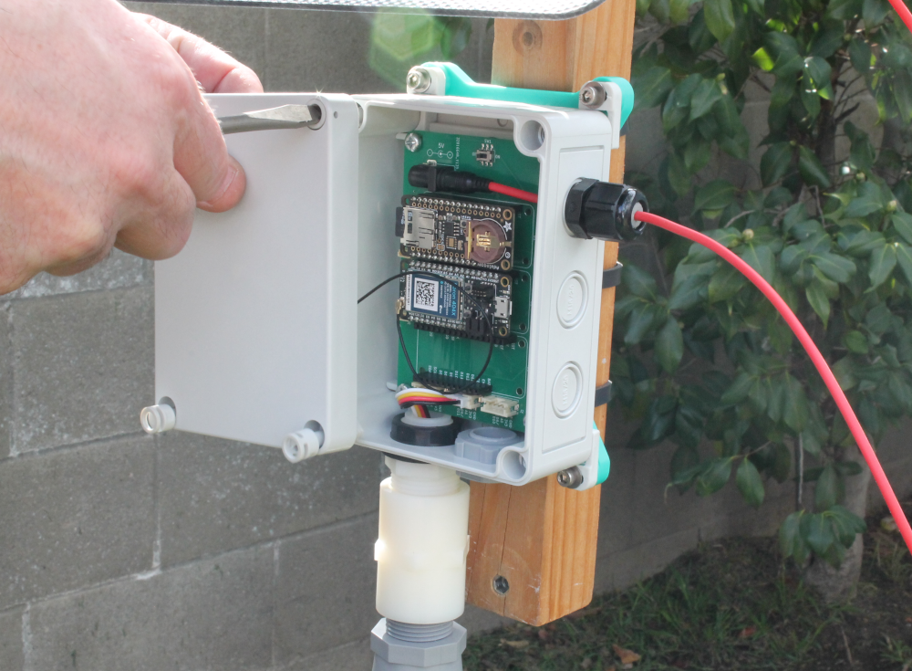
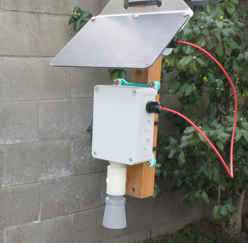
v) Double-check all 3 enclosure entries (vent plug, distance sensor & power cable entry) are screwed/tightened down. You may want to do some final cable management as the last step, such as tucking the extra cable into the solar system.
