Rodeostat assembly notes
The Rodeostat potentiostat is assembled and does not require these additional steps. These instructions are included for general interest and for anyone making their own Rodeostat.
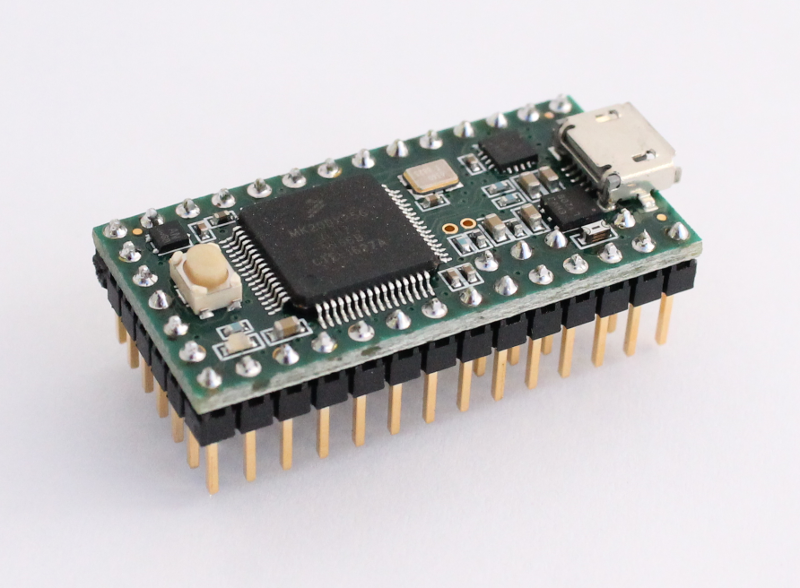
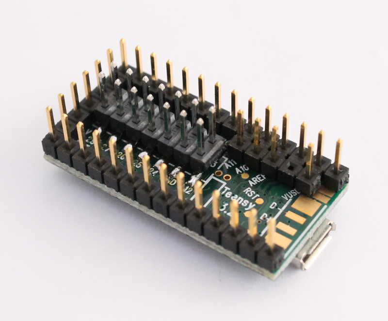
Teensy 3.2 Headers
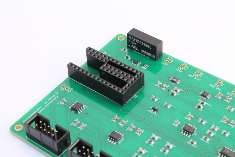
Solder the Teensy headers onto the Rodeostat board
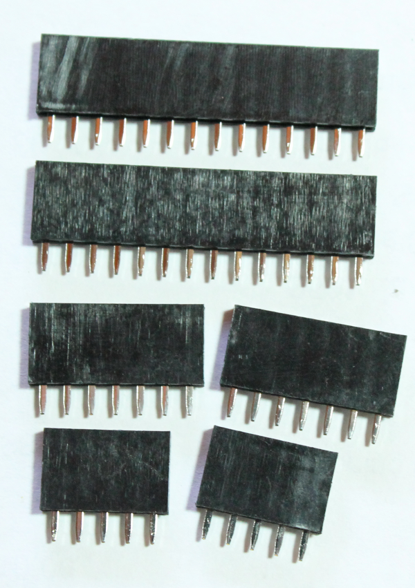
Solder the following female headers onto the Rodeostat board
- 2 x 14 pos female header, Digikey # S7012-ND
- 2 x 5 pos female header, Digikey # S6103-ND. Pull pin out of the header where appropriate on one of the 5-pos headers
- 2 x 7 pos female header, Digikey # S7005-ND

Solder pin headers onto Teensy 3.2
Solder the following pin headers onto the backside of the Teensy 3.2 board
- 1 x surface mount header for Teensy 3.2, Digikey # WM17453-ND
- 1 x 40-pos breakaway male header, Digikey # A26513-40-ND (break into 2 x 14-pos and 2 x 5-pos). Pull pin out of the header where appropriate on one of the 5-pos headers