Rodeostat FeatherWing Hardware
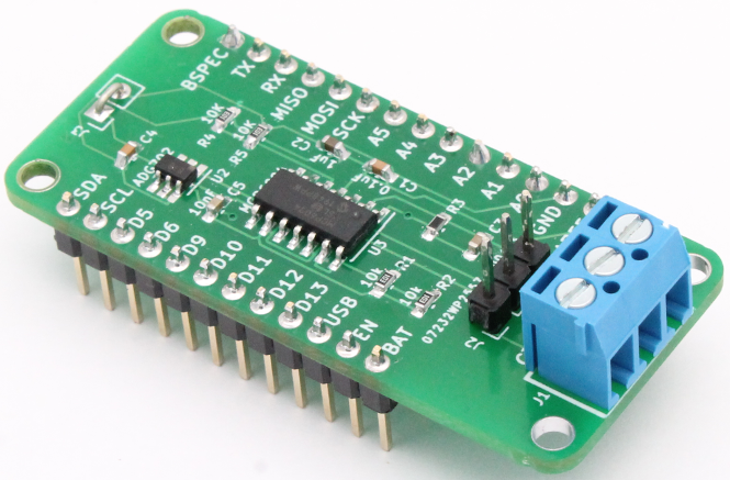
Overview
The Rodeostat FeatherWing is a potentiostat expansion board which is designed to be compatible with Adafruit's Feather/FeatherWing system. It is a single channel potentiostat which provides connections for one working, one reference and one counter electrode. It has a +/- 1.65V output range and comes in three different current range variants: +/- 10, 100, and 1000uA. As an expansion board the Rodeostat FeatherWing it is not a stand alone instrument, but rather is designed to be used in combination with a Feather development board such as Adafruit's Feather M4 Express, PyBadge, PyGamer boards. The firmware which controls the potentiostat runs on the Feather development board.
The purpose of this guide is to provide a description of the Rodeostat FeatherWing's hardware. In a later guide we will provide some example firmware for controlling the potentiostat.
Electrode connections
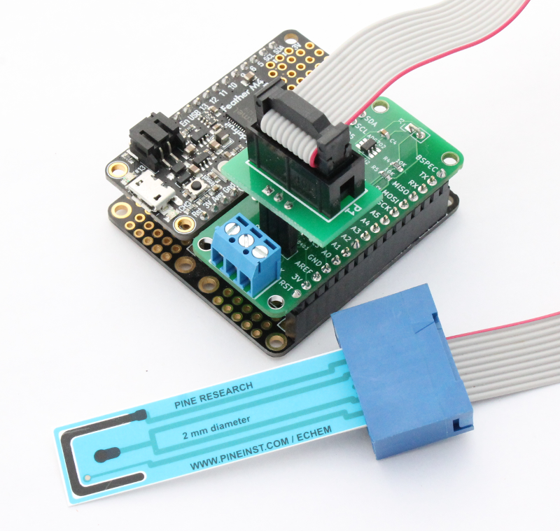
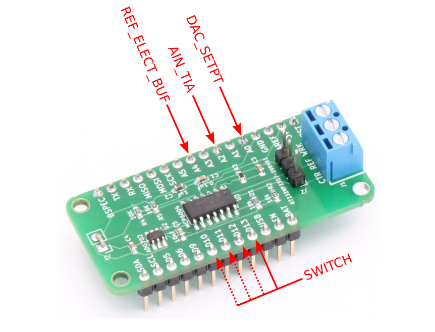
The Rodeostat FeatherWing provides a three position screw terminal and a 3-pin header for connecting the working, reference and counter electrodes. Theses connections are shown in the image below.
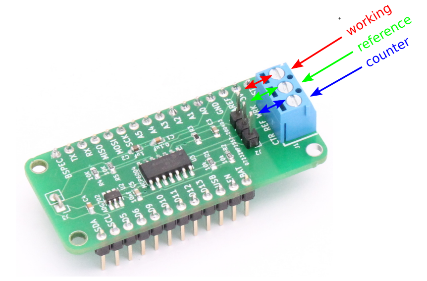
- The screw terminals are commonly used for connecting electrodes via the standard alligator clip style cables.
- The 3-pin header is commonly used for connecting to screen printed electrodes using one of our screen printed electrode adapters.
Feather connections
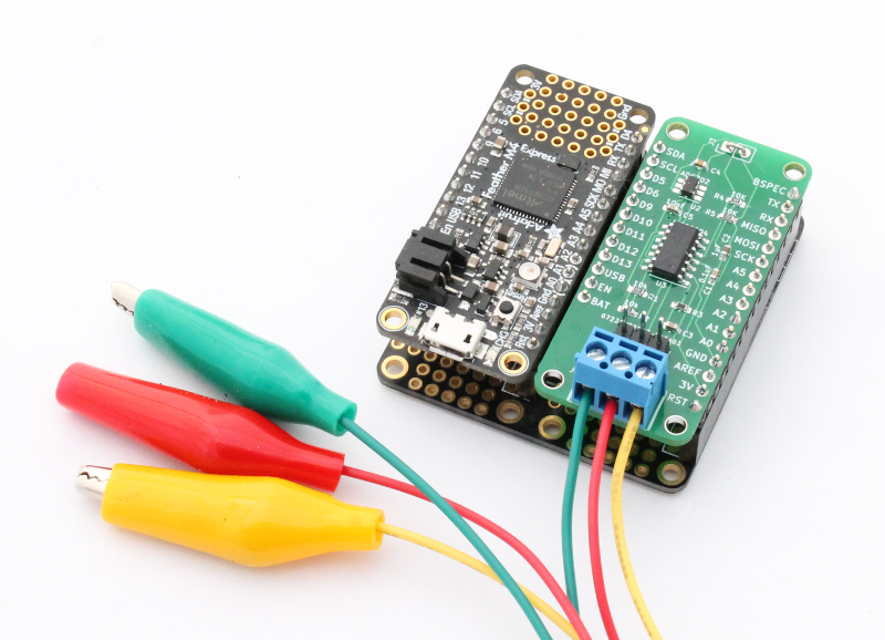
In this section we describe the connections between the Rodeostat FeatherWing and the Feather development board.
The Rodeostat FeatherWing is powered by the Feather development board and is connected to both the 3.3V and GND.
In addition there are four further connections between the Rodeostat FeatherWing and the Feather development board which are used to control the potentiostat and to sample data during trials. These connections (DAC_SETPT, AIN_TIA, REF_ELECT_BUF and SWITCH) are shown in the image below.
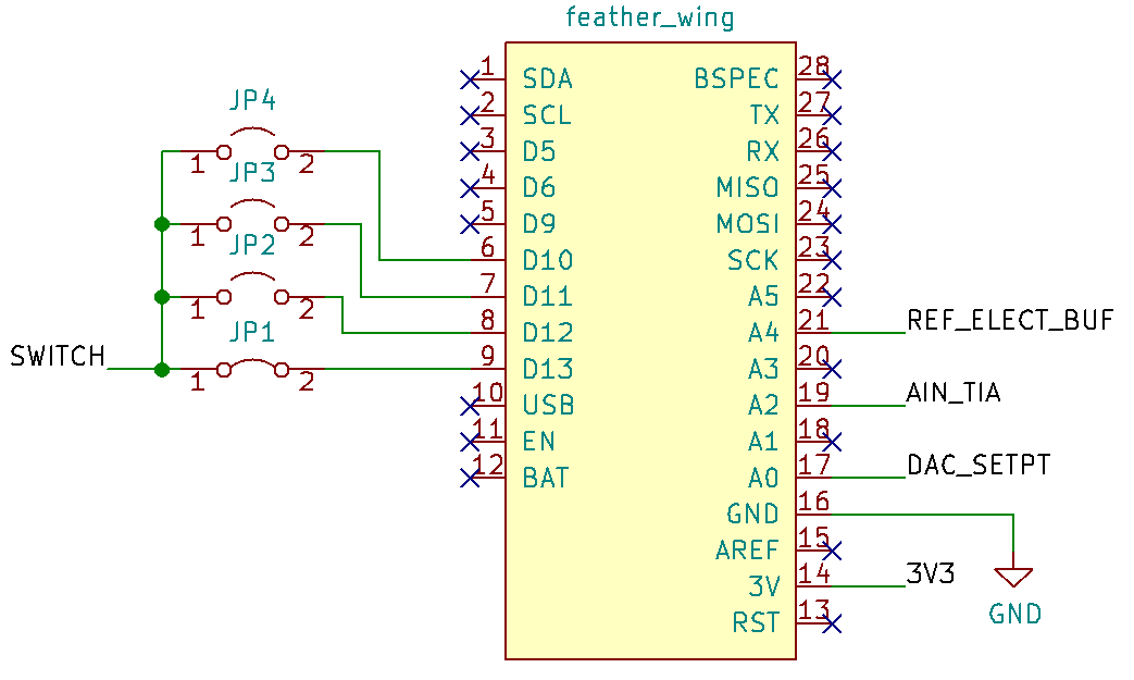
DAC_SETPT
Connected to the Feather's analog output A0, DAC_SETPT is used to control the output voltage of the potentiostat i.e. the voltage between the working and reference electrodes. Note, the potentiosat uses a virtual ground of 1.65V as the ground voltage for the test cell. This must be taken into account when setting the output voltage using the analog output A0. For example, in order to set the output voltage of the potentiostat to the value X the voltage of the analog ouput A0 must be set to 1.65V + X.
AIN_TIA
Connected to the Feather's analog input A2, AIN_TIA is the output voltage of the potentiostat's transimpedance amplifier. The transimpedance amplifier is a current to voltage converter and is used to measure the current flowing in/out of the working electrode. In the section on "Potentiostat Operation" we describe how to convert the measured voltages into current values.
REF_ELECT_BUF
Connected to the Feather's analog input A4, REF_ELECT_BUF is the output voltage of the reference electrode's unity gain buffer amplifier. It can be used to measure the voltage between the working and reference electrodes. Again as with DAC_SETPT it is necessary to take into account the virtual ground (1.65V) when calculating this voltage. For example, if Y is the analog voltage sampled from A4 then the voltage between the working and reference electrodes is Y - 1.65V.
SWITCH
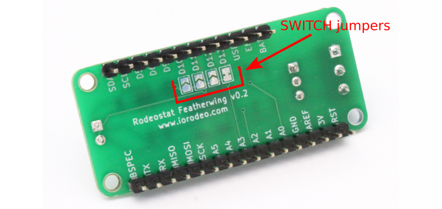
Connected to the Feather's digital output (D13), SWITCH is the input voltage to a digital switch used to connect/disconnect the counter electrode to/from the control amplifier output. When the digital output (D13) is LOW the switch is closed at the counter electroded is connectedto the control amplifier output. Alternatively, when the digital output (D13) is HIGH the switch is open and the counter electrode is disconnected from control amplifier output. The switch can (optionally) be changed to another digital pin using the solder jumpers on the underside of the board. To do this you cut the default trace and bridge the sodler jumper to connect to the desired pin. Other pin options are D12, D11, and D10.
The solder bridge jumpers on the underside of the board can be used to change the digital pin used to connect to SWITCH. The location of the SWITCH jumpers are shown in the image below.
Potentiostat operation
In this section we describe the basic procedure for operating the Rodeostat FeatherWing from the Feather development board describing the operational steps at a hardware level. It is assumed that the counter, working and reference electrodes are connected and that at the start of the procedure the switch is diconnected. Programming language specifics will be covered in a later blog post.
The basic procedure for operating the potentiostat is as follows:
- Set output voltage to the desired inital value using DAC_SETPT via analog output A0. Recall that to do this we must take into account the fact that the test cell uses a virtual gound (VGND) of 1.65V. For example, suppose the desired initial output output voltage for the potentiostat is -0.1V. In order to acheive this we would set analog output A0 so that it has a voltage of VGND - 0.1V = 1.65V - 0.1V = 1.55V.
- Connect the counter electrode to the output of the control amplifier. This is done by setting the digital output connected to SWITCH (D13 by default) to LOW. At this point the voltammetric test has started.
- During the voltammetric test the output voltage of the potentiostat is adjusted, using DAC_SETPT (A0), in time steps as required by the test type e.g. linear sweep, cyclic voltammetry, etc. Again, as in step 1, the virutal ground, VGND, must be taken into account when setting these values using the analog output. As the output voltages are adjusted, the output of the transimpedance amplifier, AIN_TIA, can be sampled using analog input A2 providing a meaurement of the current flow in/out the working electrode. Similary, the output of the reference electrode's unity gain amplifier (REF_ELECT_BUF) can be sampled uing analog input A4 providing a measurement of the voltage between the working and reference electrodes.
- Finally, when the voltammetric test is complete, the counter electrode is disconnected from the control amplifier using SWITCH by setting the digital output (D13 by default) to HIGH.
Circuit Description
In this section we describe the circuits which make up the Rodeostat FeatherWing's potentiostat. The full schematic for the potentiostat can be downloaded here.
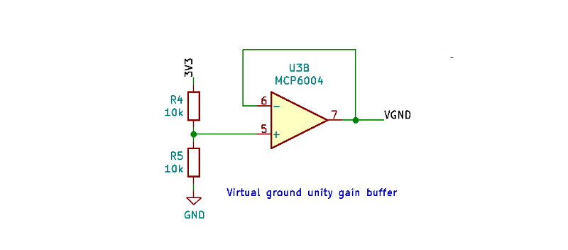
Virtual ground
The potentiostat is powered from 3.3V provided by the Feather development board. As many voltammetric tests require bipolar output voltages, the potentiostat uses a virtual ground VGND at 1.65V for the test cell. This value is convenient as it is halfway between the 3.3V power input and the feather's ground. The virtual ground, VGND, is created using voltage-divider made from two 10k (0.1% tolerance) resistors and a unity gain buffer amplifier as shown below.
Reference electrode
The signal from the working electrode in the test cell, REF_ELECT, is connected to a unity gain buffer amplifier (voltage follower) to produce a buffered version of this sigal, REF_ELECT_BUF. This is done to prevent the subsequent connections in the potentiostat from an effect the REF_ELECT signal. The buffer version of this signal is then sent to the control amplifier where it is used as part of the potentiostats feedback loop. It is also sent to analog input A4 on the Feather development board where it can be sampled. The schematic for the reference electrode buffer amplifier is shown in the image below.

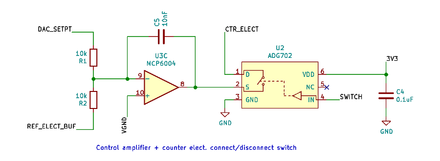
Control amplifier
The control amplifier uses a feedback loop to maintain the desired voltage relationship between the working and reference electrodes (the output voltage) during voltammetric tests. It does this by adjusting the potential of the counter electrode. It uses Both the DAC_SETPT and REF_ELECT_BUF signals as inputs. If these two signals are not symmetric with respect to the virtual ground, the control amplifier will adjust potentional of the counter electrode until they are. The schematic for the control amplifier is shown in the image below. Also included in the schematic is the digitally controlled switch which connects/disconnects the counter electrode to the control amplifier output.
Transimpedance amplifier
The transimpedance amplifier is a current to voltage converter which is converts the current flowing in/out of the working electrode into a voltage (AIN_TIA) so that it can be measured using used to measure using analog input A2. The output voltage of the transimpedance amplifier is proportional to the current flowng in/out of the working electrode. The schematic for the transimpedance amplifier is shown below.
The value of the resistor $R_3$ determines the constant of proportionality between the current flowing in/out of the working electrode, $I$, and the output voltage of the transimpedance amplifier, AIN_TIA. The output voltage is given by
$$
\texttt{AIN_TIA} = \texttt{VGND} + I R_3
$$
where the sign of $I$ is taken to be positive for current flowing out of the working electrode and negative for current flowing in to the working electrode.
The value of $R_3$ = 16.5k, which is shown in the schematic above, gives a current range of +/-100uA. Changing the value of this resistor will change the full scale current range of the device. For current ranges of +/-10uA and +/-1000uA the values of $R_3$ are 165k and and 1.65k respectively.
Typically, the analog input voltage AIN_TIA is measured using analog input A2 on the Feather development board during voltammetric trials. This measured voltage can be converted into a current by inverting the formula given above as follows
$$
I = \frac{\texttt{AIN_TIA} - \texttt{VGND}}{R_3}.
$$
In the next blog post we will cover some example firmware, which runs on the Feather development board, for controlling the potentiostat.
Comments ()