Rodeostat Multiplexer
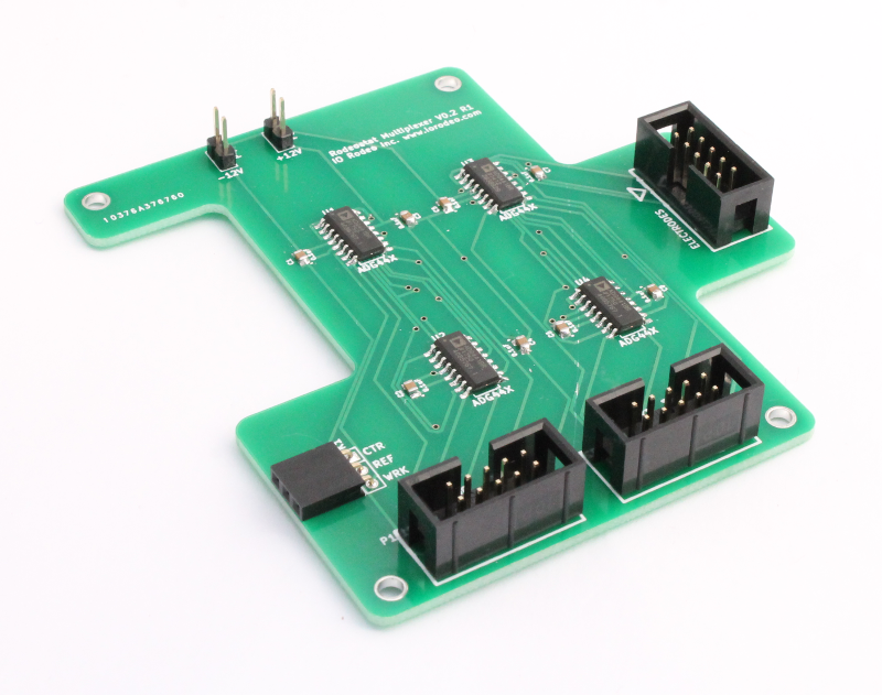
The Rodeostat Multiplexer is an expansion board for the Rodeostat potentiostat which enables it to be used with up to seven working electrodes simultaneously. This is achieved by adding a multiplexing switch to the single working electrode channel on the Rodeostat. This switch operates under control of the Rodeostat firmware and enables its single working electrode channel to be seemlessly switched between seven additional working electrode channels. The multiplexing is performed using a special make-before-break switch which ensures that the current flow through each working electrode is uninterrupted during the switching activity.
Hardware Overview
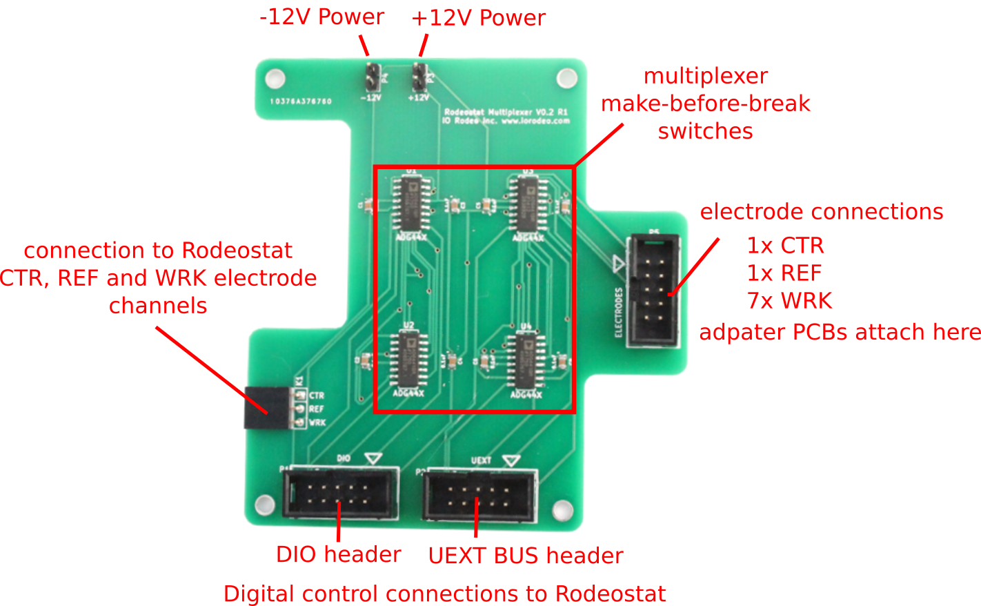
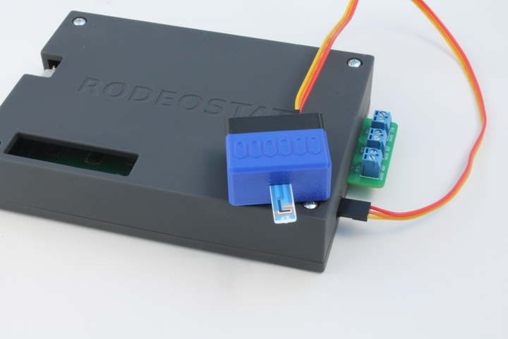
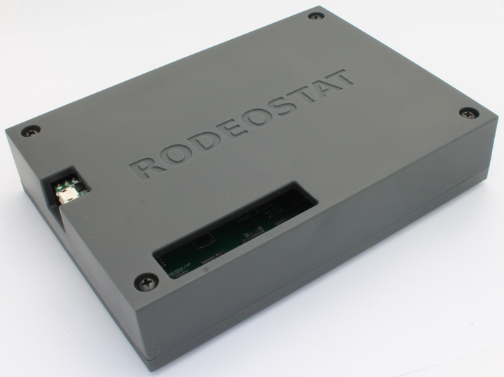
An image of the Rodeostat multiplexer is shown below with various features highlighted.
Connections to Rodeostat
As the multiplexer is designed to work with the Rodeostat it needs to connect to it in various ways. The connections are summarized below.
- The Rodeostat provides power to the multiplexer via the +/-12V connections on the 2-pin male headers (see image above, top of board).
- The multiplexer's make-before-break switches are controlled by digital signals from the Rodeostat which connect via the 5x2 shrouded headers, labeled DIO and BUS/UEXT, (see image above, bottom of board).
- The Rodeostat's electrode channels, counter (CTR), working (WRK) and reference (REF) are connected to the multiplexer via the 3-pin female header (see image above, left side of board).
For detailed assembly instructions illustrating how to connect the multiplexer expansion board to the Rodeostat see the the Rodeostat Multiplexer getting started guide.
Electrode connections
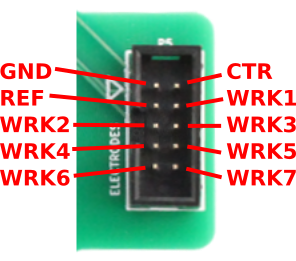
The electrode connections on the Rodeostat multiplexer are found on the 5x2 shrouded header, labeled ELECTRODES (see image above, right side of board). An image of this header with the pins labeled is shown in the image below.
-
The counter (CTR) and reference (REF) electrode connections on the multiplexer's 5x2 header connects to the counter (CTR) and reference (REF) electrode channels on the Rodeostat via digital switches. This enables the counter electrode to be completely disconnected from the potentiostat, via the firmware, when not in use.
-
The working electrode connections (WRK1, WRK2, ... WRK7) on the multiplexer's 5x2 header connnect to the working electrode channel (WRK) on the Rodeostat via make-before-brake switches. The working electrode connections can be completely disconnected from the Rodeostat and connected individually to the Rodeostat's WRK channel.
-
During voltametric tests the Rodeostat's firmware automatically handles connecting and disconnecting the electrodes as well as the sequencing of the connections of the working electrodes WRK1, ..., WRK7 to the Rodeostat's WRK channel for sampling.
Electrode adapter PCBs
In order to connect the 5x2 ELECTRODES header on the multiplexer to the electrodes in a test cell an adapter PCB is required. There are currently two electrode adapter PCBs available as shown in the image below:
- 3-Pin electrode adapter
- Screw terminal electrode adapter
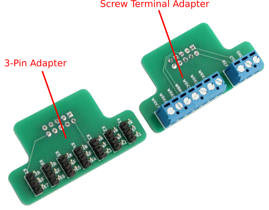
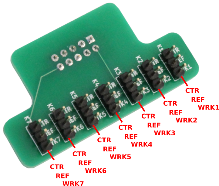
3-pin electrode adapter
The 3-pin electrode adapter PCB is for use with IO Rodeo's screen printed electrode adapters and dummy cells. It has seven 3-pin electrode connections with counter (CTR), reference (REF) and working electrode connections (WRK1, ... WRK7).
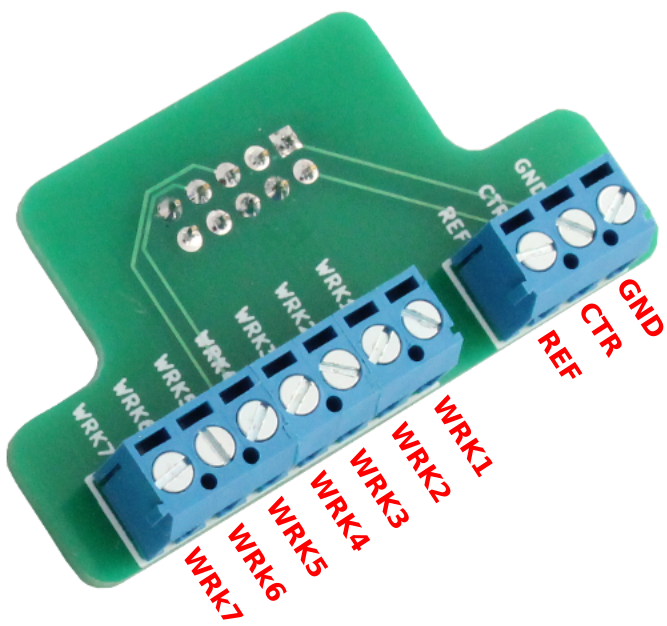
Screw terminal electrode adapter
The screw terminal electrode adapter PCB is for use with standard alligator clip style cables or any electrode which can be used with a screw terminal. It has ground (GND), counter (CTR), reference (REF) and working electrode connections (WRK1, ... WRK7).
Schematic
An image of the Rodeostat Multiplexer schematic is shown below.
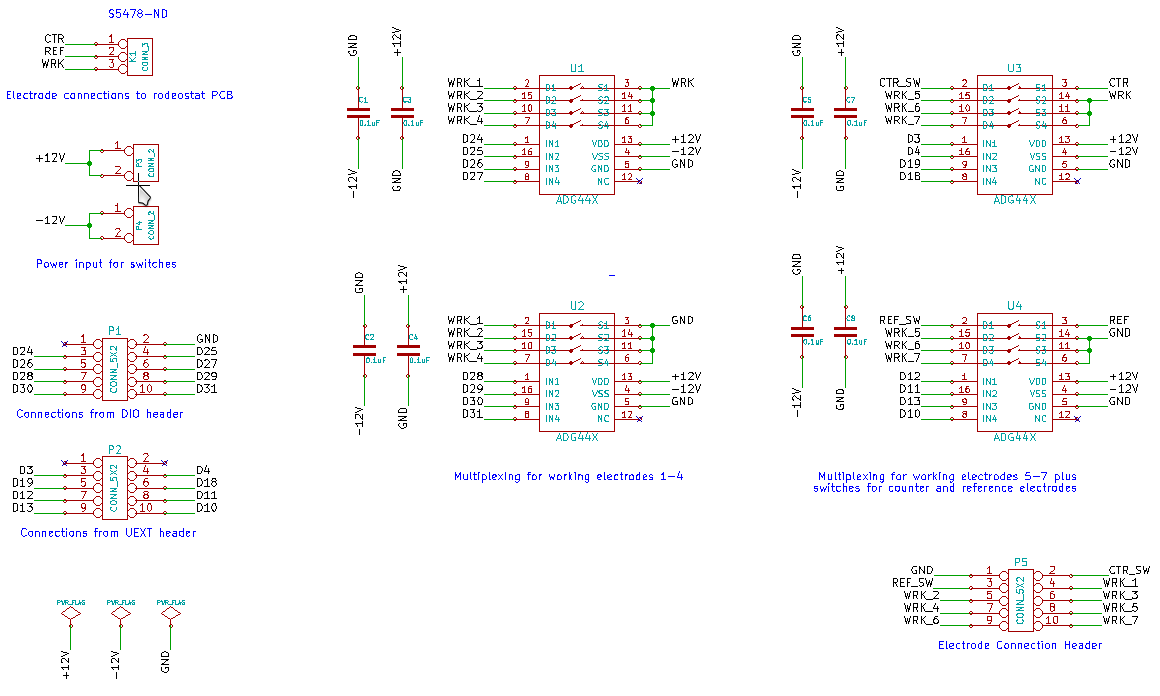
A PDF version of the schematic can be downloaded from here.
Design files
The Rodeostat multiplexer is designed using Open Source Electronics Design software KiCad. The complete set of design files, including all revisions, for the multiplexer design can be found in IO Rodeo's potentiostat repository on Bitbucket. In particular, the design files for the multiplexer can be found in the "hardware/pcbs/multiplexer" subdirectory.
Comments ()